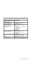


Factory-Installed Drive Devices
Use this check procedure to test any factory-installed drives.
Attention: The customer might have customized settings in the Setup Utility
(other than default settings) on the computer you are servicing. Running the
Setup Utility might alter those settings. Note the current settings and verify
that the customer settings are in place when service is complete.
Note: If you cannot access the hard disk drive or load a diskette from drive
A or load a CD from the CD/DVD-ROM drive, make sure the Setup
Utility has the startup sequence set with
Hard Disk
,
Diskette
, and
CD/DVD-ROM
enabled.
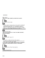
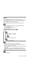
If the number of diskette drives shown in the Installed Devices list is
not correct:
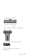
1. Check the installation of the drive ribbon cable to the system board.
Note: If the drive is installed in the Media Console, check the drive
ribbon cable from the system board to the host card and from
the drive to the client card. Also check the Media Console
cable.
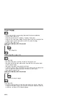
2. Check the voltages to the diskette drive with the power on (see “Power
Supply” on page 2-34).
3. Check the installation of the Media Console cable (Type 2142) on the
system board.
4. Try to correct the drive setting in the (SETUP) option in the Setup Utility.
5. Run the “Diagnostics and Utilities Device Presence Test” on page 2-43.
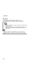
If you can correct the Installed Devices list, but cannot complete the
Diagnostics and Utilities test for that device, replace FRUs, in the following
order, until the problem goes away:
1. Diskette drive
2. Diskette drive cable (if continuity check fails)
3. Media Console host card (Type 2142)
4. Media Console client card (Type 2142)
5. Media Console (Type 2142)
6. System board
If the number of hard disk drives or CD/DVD-ROM drives shown in the
Installed Devices list is not correct:
1. Check the installation of the drive ribbon cable to the system board. Be
sure that Hard Disk Drive 1 and Hard Disk Drive 2 in the Setup Utility
are connected to the primary hard disk drive connector J8 on the Type
Check Procedures
2-47
Summary of Contents for Aptiva 2140
Page 2: ......
Page 8: ...vi...
Page 24: ...xxii...
Page 26: ...xxiv...
Page 128: ...3 14...
Page 132: ...2010 Cover Do not lift the cover too high as the tabs might break 4 4...
Page 134: ...Figure 4 2 3 5 In Cage 4 6...
Page 136: ...JP7 JP6 JP4 J2 J1 Figure 4 4 Console cable removal 4 8...
Page 138: ...Figure 4 7 Removing the console 4 10...
Page 139: ...Figure 4 8 Removing the console bottom plate Figure 4 9 Console spring Repair Information 4 11...
Page 170: ...6 2...
Page 174: ...Assembly 2 Machine Type 2140 System Unit Interior SL A 1 3 4 5 6 2 7 4...
Page 178: ...Assembly 4 Machine Type 2142 System Unit Interior SL A 1 3 4 5 7 6 2 7 8...
Page 181: ...Assembly 5 Diskette Hard Disk Drives and Zip Drive 3 1 4 4 4 2 Parts Catalog 7 11...
Page 185: ...Assembly 7 CD DVD ROM Drive Modem and TV Cards 3 5 1 2 4 6 Parts Catalog 7 15...
Page 196: ...8 4...
Page 206: ...B 8...
Page 211: ......


