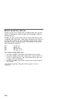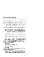
(continued)
A-1 system board, and J25 on the Type A-2 system board.
2. Check the hard disk drive jumper settings (see “Parts/Test Point
Locations” on page 5-1).
3. Check the voltages to the disk drive power connectors with the power
on (see “Power Supply” on page 2-34).
4. Try to correct the drive setting in the 3 (SETUP) option in the Setup
Utility.
5. Review the IDE Drive Info under Hardware Info in the Setup Utility.
6. Restart the system and check the Setup Utility.
7. In the Setup Utility, check that the correct drive size is set for the
flagged drive shown in the Installed Devices list.
If any drive is flagged as
Not Installed
, check the connector and
cable for that drive.
If the first drive is flagged as
Not Installed
, replace the primary
drive.
If all drives are flagged as
Not Installed
, replace the primary drive.
If any drive (other than the first drive) is flagged as
Not Installed
,
replace that drive.
If the problem remains, check the continuity on the drive cable and
replace the cable if necessary. If that does not fix the problem,
replace the system board.
8. If an upgrade processor is installed, make sure that the processor speed
shown is correct.
Note: The CD/DVD-ROM must be the last device installed and jumpers
set correctly to be listed in the Setup Utility. See “Hard Disk
Drive Jumper Settings” on page 5-10.
Also ensure the CD/DVD-ROM cable is installed in connector
J30 on the Type A-1 system board and in connector J11 on the
Type A-2 system board.
If any other adapter or device is flagged as
Not Installed
, run the
Setup program.
Check to see if any adapter or device is set to a conflicting address with any
other adapter or device. Also be sure that any adapter or device missing
from the list is not set to
Disabled
.
Note: If you cannot add a missing adapter or device to the list, the
diagnostic code for the missing adapter or device is not on the
diagnostic CD. Run the diagnostics provided with that device.
2-48
Summary of Contents for Aptiva 2140
Page 2: ......
Page 8: ...vi...
Page 24: ...xxii...
Page 26: ...xxiv...
Page 128: ...3 14...
Page 132: ...2010 Cover Do not lift the cover too high as the tabs might break 4 4...
Page 134: ...Figure 4 2 3 5 In Cage 4 6...
Page 136: ...JP7 JP6 JP4 J2 J1 Figure 4 4 Console cable removal 4 8...
Page 138: ...Figure 4 7 Removing the console 4 10...
Page 139: ...Figure 4 8 Removing the console bottom plate Figure 4 9 Console spring Repair Information 4 11...
Page 170: ...6 2...
Page 174: ...Assembly 2 Machine Type 2140 System Unit Interior SL A 1 3 4 5 6 2 7 4...
Page 178: ...Assembly 4 Machine Type 2142 System Unit Interior SL A 1 3 4 5 7 6 2 7 8...
Page 181: ...Assembly 5 Diskette Hard Disk Drives and Zip Drive 3 1 4 4 4 2 Parts Catalog 7 11...
Page 185: ...Assembly 7 CD DVD ROM Drive Modem and TV Cards 3 5 1 2 4 6 Parts Catalog 7 15...
Page 196: ...8 4...
Page 206: ...B 8...
Page 211: ......

