


(continued)
004 (continued)
Replace the monitor.
005
Check the monitor I/O signal cable. Replace if defective.
– or –
Replace the system board.
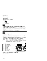
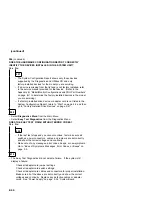
006
(From step 002)
– Power-off the system unit and monitor.
– Unplug the monitor I/O signal cable from the system unit.
– Power-on the system unit and monitor.
DOES THE SCREEN CHANGE FROM BLACK (WITH MONITOR
POWER-OFF) TO THE APPROPRIATE RASTER OR WHITE SCREEN AS
DESCRIBED IN THE DISPLAY SELF TEST?
Yes No
007
– Replace the monitor.
008
– Power-off the system unit.
– Reconnect any disconnected cables.
– Power-on the system unit.
IS THE SCREEN READABLE?
Note: If the screen shows a blinking cursor with no memory count running,
answer this question “No.”
Yes No
009
– Replace the system board
010
– Press Esc.
– Select Diagnostics from the Main Menu.
– Select Interactive Tests from the menu.
– Select Video from the menu.
(Step 010 continues)
2-54
Summary of Contents for Aptiva 2140
Page 2: ......
Page 8: ...vi...
Page 24: ...xxii...
Page 26: ...xxiv...
Page 128: ...3 14...
Page 132: ...2010 Cover Do not lift the cover too high as the tabs might break 4 4...
Page 134: ...Figure 4 2 3 5 In Cage 4 6...
Page 136: ...JP7 JP6 JP4 J2 J1 Figure 4 4 Console cable removal 4 8...
Page 138: ...Figure 4 7 Removing the console 4 10...
Page 139: ...Figure 4 8 Removing the console bottom plate Figure 4 9 Console spring Repair Information 4 11...
Page 170: ...6 2...
Page 174: ...Assembly 2 Machine Type 2140 System Unit Interior SL A 1 3 4 5 6 2 7 4...
Page 178: ...Assembly 4 Machine Type 2142 System Unit Interior SL A 1 3 4 5 7 6 2 7 8...
Page 181: ...Assembly 5 Diskette Hard Disk Drives and Zip Drive 3 1 4 4 4 2 Parts Catalog 7 11...
Page 185: ...Assembly 7 CD DVD ROM Drive Modem and TV Cards 3 5 1 2 4 6 Parts Catalog 7 15...
Page 196: ...8 4...
Page 206: ...B 8...
Page 211: ......


