


Command Line Options
To enter PC-Doctor commands:
Note: Before beginning, ensure that Suspend Timer is disabled in the
Setup Utility.
1. Install the Diagnostics and Utilities CD in the CD/DVD-ROM drive.
2. Power-off, then power-on the system unit.
3. Do not press F1 during POST.
4. If any POST errors appear after POST, make a note of the errors and
press the Esc key.
5. When the “Aptiva Diagnostics and Utilities Menu” screen is displayed,
type: zero for a DOS prompt, then change the DOS prompt to G: or the
drive letter designated for the CD/DVD-ROM.
6. Type CD\PCDR to get the the PCDR directory.
7. Type PCDR/XX (where /XX represents one of the following from the list
below) then press Enter.
Command
Action
/AN
Enables automatic testlog numbering. A sequential number
will be added to testlogs automatically. This number is stored
in the file PCDR.NUM, which can be edited using the text
editor. PC-Doctor will automatically add a testlog number if the
file PCDR.NUM exists. To disable this feature, you must
delete the PCDR.NUM file.
/BA:xx
Start batch mode testing of overlay number "xx". The overlay
number must be in the range of 1- 10. For this switch to be
useful, it should be combined with the "/PR:nnnn" switch and
possibly also the /EO and /HE switches. At the end of batch
mode testing, PC-Doctor returns with an ERRORLEVEL that is
set to 0 for no errors, 1 if any tests failed, or 2 if testing was
aborted.
/DJ
Direct Joystick I/O. This will force PC-Doctor to read joystick
status and position directly from the hardware.
/EO
Log error only. If selected, PC-Doctor will only log tests that
produce a FAILED result. You can use this switch to bypass
PASSED and N/A test results in order to produce shorter test
logs.
/HE
Enables halt-on-errors mode. If PC-Doctor encounters a failed
diagnostic test, it asks the user if it should continue or abort
testing.
Diagnostic Aids
3-9
Summary of Contents for Aptiva 2140
Page 2: ......
Page 8: ...vi...
Page 24: ...xxii...
Page 26: ...xxiv...
Page 128: ...3 14...
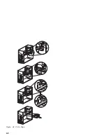
Page 132: ...2010 Cover Do not lift the cover too high as the tabs might break 4 4...
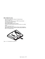
Page 134: ...Figure 4 2 3 5 In Cage 4 6...
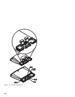
Page 136: ...JP7 JP6 JP4 J2 J1 Figure 4 4 Console cable removal 4 8...
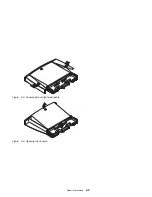
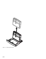
Page 138: ...Figure 4 7 Removing the console 4 10...
Page 139: ...Figure 4 8 Removing the console bottom plate Figure 4 9 Console spring Repair Information 4 11...
Page 170: ...6 2...
Page 174: ...Assembly 2 Machine Type 2140 System Unit Interior SL A 1 3 4 5 6 2 7 4...
Page 178: ...Assembly 4 Machine Type 2142 System Unit Interior SL A 1 3 4 5 7 6 2 7 8...
Page 181: ...Assembly 5 Diskette Hard Disk Drives and Zip Drive 3 1 4 4 4 2 Parts Catalog 7 11...
Page 185: ...Assembly 7 CD DVD ROM Drive Modem and TV Cards 3 5 1 2 4 6 Parts Catalog 7 15...
Page 196: ...8 4...
Page 206: ...B 8...
Page 211: ......


