


Removals and Replacements—Machine Type 2140,
2142
See Safety Notice 1: Translation on page xi
Before removing any FRU, power-off the computer, unplug all power
cords from electrical outlets, then disconnect any interconnecting cables.
Attention: The system board, processors, adapter cards, DIMMs, and
upgrade processors can be damaged by electrostatic discharge. Use an
electrostatic discharge (ESD) strap to establish personal grounding. If you
don’t have an ESD strap, establish personal grounding by touching a ground
point with one hand before touching the static-sensitive FRUs.
Note: Machine Type 2140, 2142 might contain drives and devices not
illustrated in this book. Follow replacement instructions for the same size
device if in doubt. See Appendix B, “Model/Monitor Configurations and FRU
Part Numbers” on page B-1 for exact model configurations.
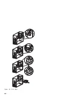
The arrows in the removals and replacements procedures show the direction
of movement to remove a field-replaceable unit (FRU), to turn a screw, or to
press a tab to release the FRU.
Begin all removals by removing the cover (and rear cover, if applicable).
When other FRUs must be removed prior to removing the failing FRU, they
are listed at the top of the page. Go to the removal procedure for each FRU
listed, remove the FRU, and then continue with the removal of the failing
FRU.
To replace a FRU, reverse the removal procedure and follow any notes that
pertain to replacement. See “Parts/Test Point Locations” on page 5-1 for
internal cable connection and arrangement information.
Before disconnecting any cables, note their locations. Reinstall any new
FRUs with cables in the same locations.
4-2
Summary of Contents for Aptiva 2140
Page 2: ......
Page 8: ...vi...
Page 24: ...xxii...
Page 26: ...xxiv...
Page 128: ...3 14...
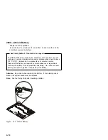
Page 132: ...2010 Cover Do not lift the cover too high as the tabs might break 4 4...
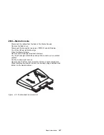
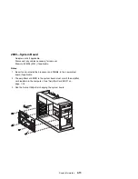
Page 134: ...Figure 4 2 3 5 In Cage 4 6...
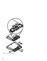
Page 136: ...JP7 JP6 JP4 J2 J1 Figure 4 4 Console cable removal 4 8...
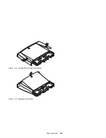
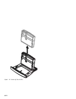
Page 138: ...Figure 4 7 Removing the console 4 10...
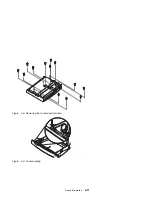
Page 139: ...Figure 4 8 Removing the console bottom plate Figure 4 9 Console spring Repair Information 4 11...
Page 170: ...6 2...
Page 174: ...Assembly 2 Machine Type 2140 System Unit Interior SL A 1 3 4 5 6 2 7 4...
Page 178: ...Assembly 4 Machine Type 2142 System Unit Interior SL A 1 3 4 5 7 6 2 7 8...
Page 181: ...Assembly 5 Diskette Hard Disk Drives and Zip Drive 3 1 4 4 4 2 Parts Catalog 7 11...
Page 185: ...Assembly 7 CD DVD ROM Drive Modem and TV Cards 3 5 1 2 4 6 Parts Catalog 7 15...
Page 196: ...8 4...
Page 206: ...B 8...
Page 211: ......


