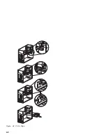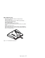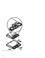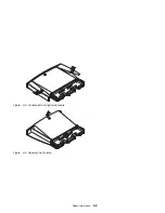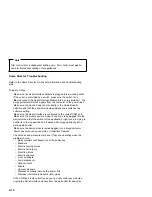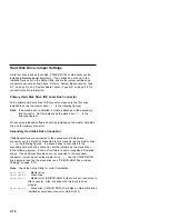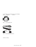
Handling ESD-Sensitive Parts
Many products use parts that are known to be sensitive to electrostatic
discharge (ESD). To prevent damage when you work with ESD-sensitive
parts, observe the following instructions. Do these in addition to taking all
the usual precautions, such as switching off the power and unplugging the
power cord before removing adapter cards.
Keep the ESD-sensitive part in its original shipping container (a special
ESD bag) until you are ready to install the part into the machine.
Make the fewest possible movements with your body to prevent an
increase of static electricity from clothing fibers, carpets, and furniture.
Put the ESD wrist strap on your wrist. Ensure the machine is turned off.
Connect the wrist strap to the serial bracket mounting screw. This
discharges any static electricity in your body to the machine frame.
Hold the ESD-sensitive part by its edge connector shroud (cover).
Do
not touch its pins. If you are removing a pluggable module, use the
correct tool.
Do not place the ESD-sensitive part on the machine cover or on a metal
table. If you need to put down the ESD-sensitive part for any reason,
first put it into its special bag.
Machine covers and metal tables are electrical grounds. They increase
the risk of damage because they make a discharge path from your body
through the ESD-sensitive part. (Large metal objects can be discharge
paths without being grounded.)
Prevent ESD-sensitive parts from being accidentally touched by other
personnel or customers. Reinstall machine covers when you are not
working on the machine.
If possible, keep all ESD-sensitive parts in a grounded metal cabinet
(case).
Be extra careful while working with ESD-sensitive parts when
cold-weather heating is used because low humidity increases static
electricity.
4-16
Summary of Contents for Aptiva 2140
Page 2: ......
Page 8: ...vi...
Page 24: ...xxii...
Page 26: ...xxiv...
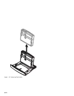
Page 128: ...3 14...
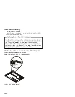
Page 132: ...2010 Cover Do not lift the cover too high as the tabs might break 4 4...
Page 134: ...Figure 4 2 3 5 In Cage 4 6...
Page 136: ...JP7 JP6 JP4 J2 J1 Figure 4 4 Console cable removal 4 8...
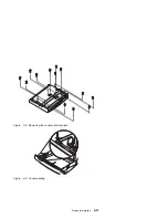
Page 138: ...Figure 4 7 Removing the console 4 10...
Page 139: ...Figure 4 8 Removing the console bottom plate Figure 4 9 Console spring Repair Information 4 11...
Page 170: ...6 2...
Page 174: ...Assembly 2 Machine Type 2140 System Unit Interior SL A 1 3 4 5 6 2 7 4...
Page 178: ...Assembly 4 Machine Type 2142 System Unit Interior SL A 1 3 4 5 7 6 2 7 8...
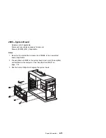
Page 181: ...Assembly 5 Diskette Hard Disk Drives and Zip Drive 3 1 4 4 4 2 Parts Catalog 7 11...
Page 185: ...Assembly 7 CD DVD ROM Drive Modem and TV Cards 3 5 1 2 4 6 Parts Catalog 7 15...
Page 196: ...8 4...
Page 206: ...B 8...
Page 211: ......


