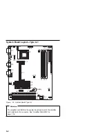
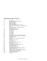
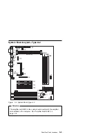
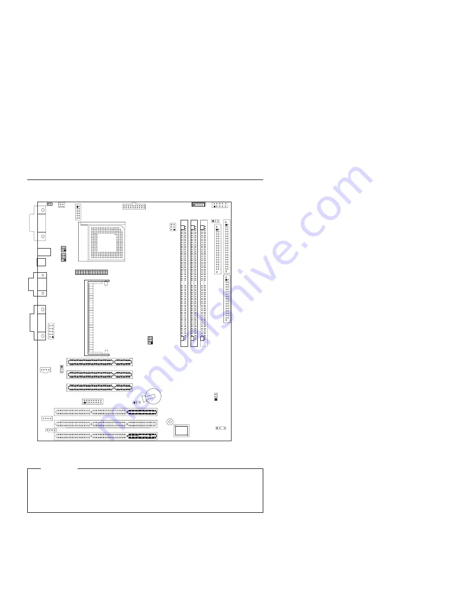
System Board Layout—Type A-1
J14
J11
JP12
J5 J6 J7
JP4
J39
J19
J20
Buzzer
Battery
Bios
Module
J21
J31
J30
J32
J41
J29
J10
J2
J24
J23
J27
JP21
JP6
J18
J17
J16
J8
J34
J1
J40
U1
JP2
JP1
JP3
JP5
JP11 J9
J33
J38
J26
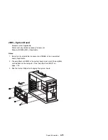
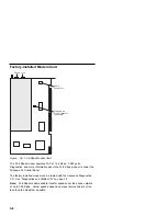
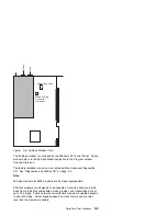
Figure
5-1. System Board Type A-1
Attention
The amplifier card BIOS in the system board must match the amplifier
card installed in the computer. See “Amplifier Card BIOS” on
page 1-16.
5-2
Summary of Contents for Aptiva 2140
Page 2: ......
Page 8: ...vi...
Page 24: ...xxii...
Page 26: ...xxiv...
Page 128: ...3 14...
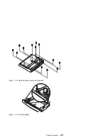
Page 132: ...2010 Cover Do not lift the cover too high as the tabs might break 4 4...
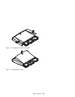
Page 134: ...Figure 4 2 3 5 In Cage 4 6...
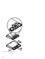
Page 136: ...JP7 JP6 JP4 J2 J1 Figure 4 4 Console cable removal 4 8...
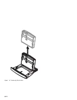
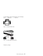
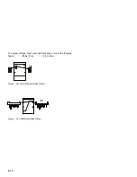
Page 138: ...Figure 4 7 Removing the console 4 10...
Page 139: ...Figure 4 8 Removing the console bottom plate Figure 4 9 Console spring Repair Information 4 11...
Page 170: ...6 2...
Page 174: ...Assembly 2 Machine Type 2140 System Unit Interior SL A 1 3 4 5 6 2 7 4...
Page 178: ...Assembly 4 Machine Type 2142 System Unit Interior SL A 1 3 4 5 7 6 2 7 8...
Page 181: ...Assembly 5 Diskette Hard Disk Drives and Zip Drive 3 1 4 4 4 2 Parts Catalog 7 11...
Page 185: ...Assembly 7 CD DVD ROM Drive Modem and TV Cards 3 5 1 2 4 6 Parts Catalog 7 15...
Page 196: ...8 4...
Page 206: ...B 8...
Page 211: ......


