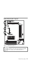
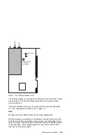
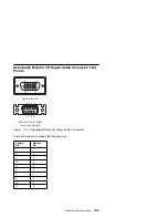
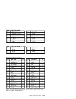

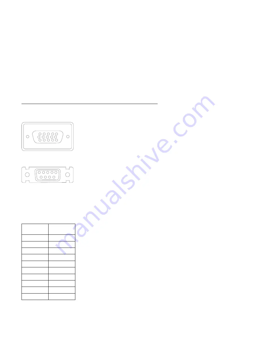
Detachable Monitor I/O Signal Cable Connector Test
Points
1 2 3 4 5
6 7 8 9
1
6
10
5
15
11
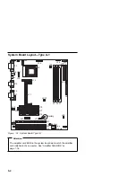
System board
Monitor end of cable
(on some models)
Figure
5-13. Detachable Monitor I/O Signal Cable Connectors
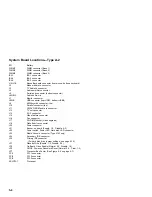
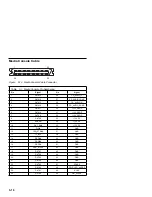
Test each connector between the following pins:
System
Pin
Monitor
Pin
1
1
2
2
3
3
13
4
14
5
6
6
7
7
8
8
10
9
11
9
Parts/Test Point Locations
5-15
Summary of Contents for Aptiva 2140
Page 2: ......
Page 8: ...vi...
Page 24: ...xxii...
Page 26: ...xxiv...
Page 128: ...3 14...
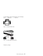
Page 132: ...2010 Cover Do not lift the cover too high as the tabs might break 4 4...
Page 134: ...Figure 4 2 3 5 In Cage 4 6...
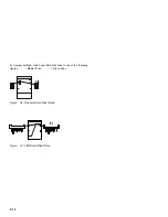
Page 136: ...JP7 JP6 JP4 J2 J1 Figure 4 4 Console cable removal 4 8...
Page 138: ...Figure 4 7 Removing the console 4 10...
Page 139: ...Figure 4 8 Removing the console bottom plate Figure 4 9 Console spring Repair Information 4 11...
Page 170: ...6 2...
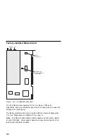
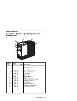
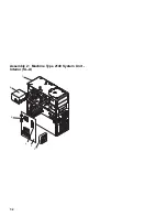
Page 174: ...Assembly 2 Machine Type 2140 System Unit Interior SL A 1 3 4 5 6 2 7 4...
Page 178: ...Assembly 4 Machine Type 2142 System Unit Interior SL A 1 3 4 5 7 6 2 7 8...
Page 181: ...Assembly 5 Diskette Hard Disk Drives and Zip Drive 3 1 4 4 4 2 Parts Catalog 7 11...
Page 185: ...Assembly 7 CD DVD ROM Drive Modem and TV Cards 3 5 1 2 4 6 Parts Catalog 7 15...
Page 196: ...8 4...
Page 206: ...B 8...
Page 211: ......


