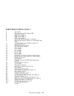
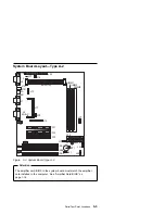
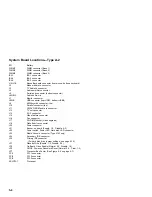
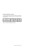
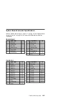
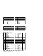

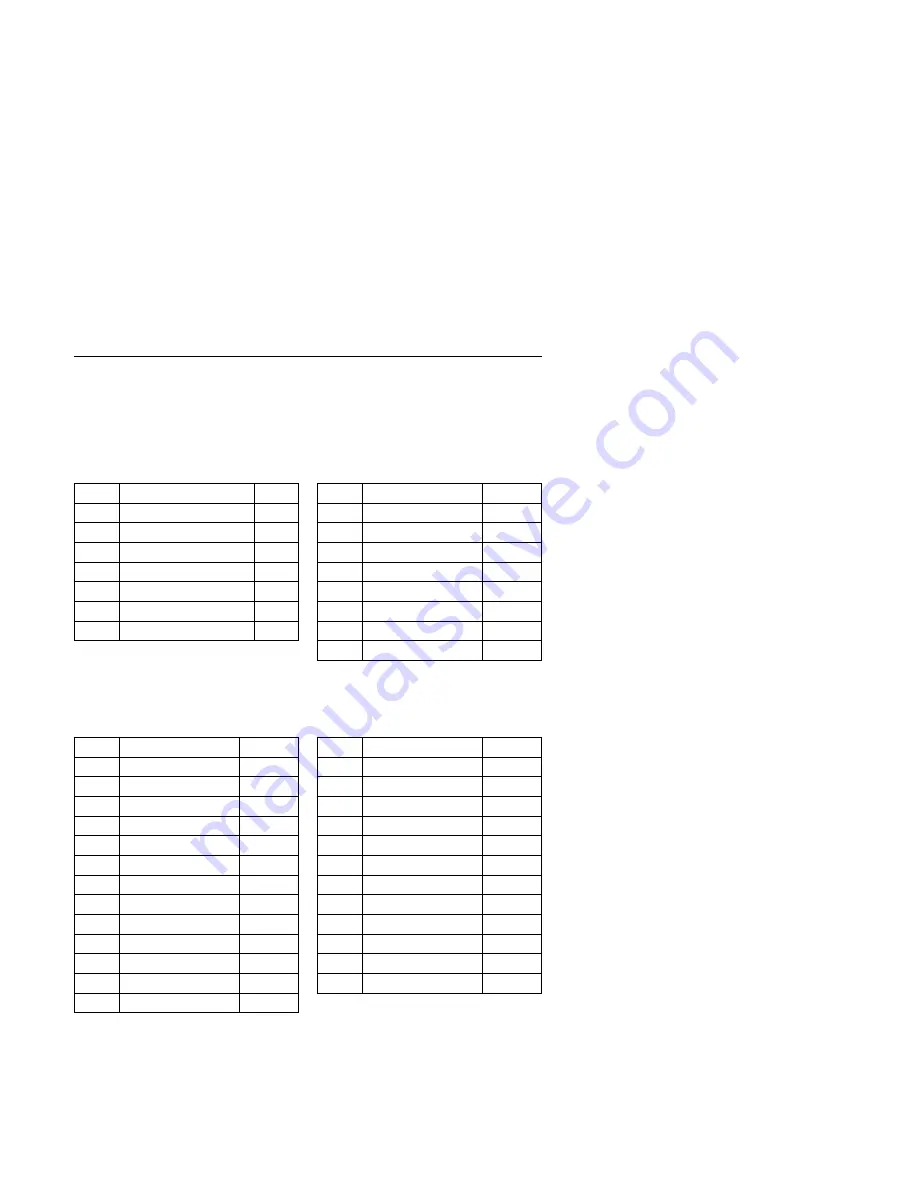
System Board Connector Specifications
Refer to “System Board Layout—Type A-1” on page 5-2 and “System Board
Layout—Type A-2” on page 5-5 for connector identification and location
information.
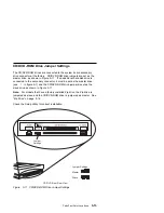
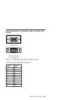
Monitor/Signal
Pin
Signal Name
I/O
Pin
Signal Name
I/O
1
Red Video
O
8
Blue Ground
2
Green Video
O
9
+5 V dc
3
Blue Video
O
10
Sync Ground
4
Monitor ID Bit 2
I
11
Monitor ID Bit 0
I
5
Sync Ground
12
SDA
I
6
Red Ground
13
Horizontal Sync
O
7
Green Ground
14
Vertical Sync
O
15
SCL
I
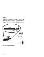
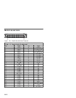
Parallel Port
Pin
Signal Name
I/O
Pin
Signal Name
I/O
1
Strobe
O
14
Auto Feed
N/A
2
Data Bit 0
I/O
15
Error
I
3
Data Bit 1
I/O
16
Initialize
O
4
Data Bit 2
I/O
17
Select (In)
O
5
Data Bit 3
I/O
18
Ground
Power
6
Data Bit 4
I/O
19
Ground
Power
7
Data Bit 5
I/O
20
Ground
Power
8
Data Bit 6
I/O
21
Ground
Power
9
Data Bit 7
I/O
22
Ground
Power
10
Acknowledge
I
23
Ground
Power
11
Busy
I
24
Ground
Power
12
Paper Empty
I
25
Ground
Power
13
Select
O
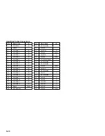
Parts/Test Point Locations
5-17
Summary of Contents for Aptiva 2140
Page 2: ......
Page 8: ...vi...
Page 24: ...xxii...
Page 26: ...xxiv...
Page 128: ...3 14...
Page 132: ...2010 Cover Do not lift the cover too high as the tabs might break 4 4...
Page 134: ...Figure 4 2 3 5 In Cage 4 6...
Page 136: ...JP7 JP6 JP4 J2 J1 Figure 4 4 Console cable removal 4 8...
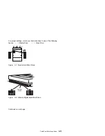
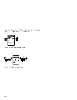
Page 138: ...Figure 4 7 Removing the console 4 10...
Page 139: ...Figure 4 8 Removing the console bottom plate Figure 4 9 Console spring Repair Information 4 11...
Page 170: ...6 2...
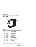
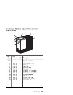
Page 174: ...Assembly 2 Machine Type 2140 System Unit Interior SL A 1 3 4 5 6 2 7 4...
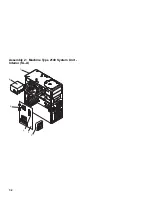
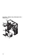
Page 178: ...Assembly 4 Machine Type 2142 System Unit Interior SL A 1 3 4 5 7 6 2 7 8...
Page 181: ...Assembly 5 Diskette Hard Disk Drives and Zip Drive 3 1 4 4 4 2 Parts Catalog 7 11...
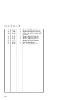
Page 185: ...Assembly 7 CD DVD ROM Drive Modem and TV Cards 3 5 1 2 4 6 Parts Catalog 7 15...
Page 196: ...8 4...
Page 206: ...B 8...
Page 211: ......


