

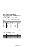


One of the following processors can be installed on the Type A-2
system board:
Pentium II-233 MHz
Pentium II-266 MHz
Pentium II-300 MHz
Pentium II-333 MHz
Power Supplies (with Power Management Features)
The power supply is a 200-W switchable high/low voltage power supply
with a variable fan speed and a connector for a detachable grounded
3-wire power cord. The power cable has four DASD connectors: one
mini power connector and three standard 4-pin connectors. The power
supply also has a non-switched appliance outlet connector.
For some countries outside the United States, the power supply might
have five standard 4-pin connectors and one mini power connector, for
a total of six DASD connectors.
To support the Power Management feature, all power supplies have a
3-wire auxiliary control cable that connects to the system board. There
is no on/off switch cable assembly for the power supplies.
Cables
All models contain one cable for hard disk drives and one cable for
diskette drives. A momentary power switch and cable assembly that
connects to the system board and a voice modem cable are also
included.
Diskette Drive—AT-type
All models contain a 3.5-in. 1.44 MB slimline diskette drive.
Some models come with a 100 MB internal Zip drive.
Multimedia
Depending on model, 24X Max or 32X Max CD-ROM,
3
or DVD-ROM
IDE/AT drive.
An audio cable
A CD/DVD-ROM drive system interface cable.
Microphone and speaker (integrated with monitor).
3
24X Max or 32X Max CD-ROM drives run at a constant speed. This causes a data
transfer rate of ten-speed (fourteen-speed for 32X) reading at the disk hub and
twenty four-speed (thirty two-speed for 32X) reading at the disk edge.
General Information
1-9
Summary of Contents for Aptiva 2140
Page 2: ......
Page 8: ...vi...
Page 24: ...xxii...
Page 26: ...xxiv...
Page 128: ...3 14...
Page 132: ...2010 Cover Do not lift the cover too high as the tabs might break 4 4...
Page 134: ...Figure 4 2 3 5 In Cage 4 6...
Page 136: ...JP7 JP6 JP4 J2 J1 Figure 4 4 Console cable removal 4 8...
Page 138: ...Figure 4 7 Removing the console 4 10...
Page 139: ...Figure 4 8 Removing the console bottom plate Figure 4 9 Console spring Repair Information 4 11...
Page 170: ...6 2...
Page 174: ...Assembly 2 Machine Type 2140 System Unit Interior SL A 1 3 4 5 6 2 7 4...
Page 178: ...Assembly 4 Machine Type 2142 System Unit Interior SL A 1 3 4 5 7 6 2 7 8...
Page 181: ...Assembly 5 Diskette Hard Disk Drives and Zip Drive 3 1 4 4 4 2 Parts Catalog 7 11...
Page 185: ...Assembly 7 CD DVD ROM Drive Modem and TV Cards 3 5 1 2 4 6 Parts Catalog 7 15...
Page 196: ...8 4...
Page 206: ...B 8...
Page 211: ......


