


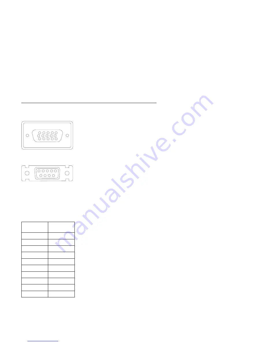
Detachable Monitor I/O Signal Cable Connector Test
Points
1 2 3 4 5
6 7 8 9
1
6
10
5
15
11
System board
Monitor end of cable
(on some models)
Figure
5-13. Detachable Monitor I/O Signal Cable Connectors
Test each connector between the following pins:
System
Pin
Monitor
Pin
1
1
2
2
3
3
13
4
14
5
6
6
7
7
8
8
10
9
11
9
Parts/Test Point Locations
5-15
Get user manuals:
Summary of Contents for Aptiva 2140
Page 2: ...Get user manuals See SafeManuals com...
Page 8: ...vi Get user manuals See SafeManuals com...
Page 24: ...xxii Get user manuals See SafeManuals com...
Page 26: ...xxiv Get user manuals See SafeManuals com...
Page 128: ...3 14 Get user manuals See SafeManuals com...
Page 134: ...Figure 4 2 3 5 In Cage 4 6 Get user manuals See SafeManuals com...
Page 136: ...JP7 JP6 JP4 J2 J1 Figure 4 4 Console cable removal 4 8 Get user manuals See SafeManuals com...
Page 138: ...Figure 4 7 Removing the console 4 10 Get user manuals See SafeManuals com...
Page 170: ...6 2 Get user manuals See SafeManuals com...
Page 196: ...8 4 Get user manuals See SafeManuals com...
Page 206: ...B 8 Get user manuals See SafeManuals com...


