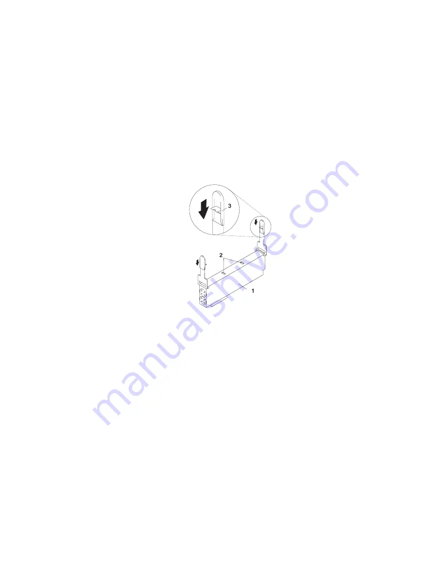
5. Grasp the ends of both power supply handles, and slide the retractable
spring-activated portion of each handle toward its hinged base. This action releases
the locking tab located on the bottom side of each release handle. See the following
illustration.
1 Power Supply
2 Locking Tab Receiver Hole
3 Retractable Spring-Activated Portion of the Handle
Chapter 4. Installing Options
125
Summary of Contents for @Server pSeries 630 6C4
Page 1: ...pSeries 630 Model 6C4 and Model 6E4 Installation Guide SA38 0605 01 ERserver IBM...
Page 2: ......
Page 3: ...pSeries 630 Model 6C4 and Model 6E4 Installation Guide SA38 0605 01 ERserver IBM...
Page 12: ...x Eserver pSeries 630 Model 6C4 and Model 6E4 Installation Guide...
Page 14: ...xii Eserver pSeries 630 Model 6C4 and Model 6E4 Installation Guide...
Page 22: ...6 Eserver pSeries 630 Model 6C4 and Model 6E4 Installation Guide...
Page 64: ...48 Eserver pSeries 630 Model 6C4 and Model 6E4 Installation Guide...
Page 148: ...132 Eserver pSeries 630 Model 6C4 and Model 6E4 Installation Guide...
Page 152: ...136 Eserver pSeries 630 Model 6C4 and Model 6E4 Installation Guide...
Page 156: ...140 Eserver pSeries 630 Model 6C4 and Model 6E4 Installation Guide...
Page 166: ...150 Eserver pSeries 630 Model 6C4 and Model 6E4 Installation Guide...
Page 179: ......
Page 180: ...IBMR Part Number 00P3937 Printed in U S A August 2002 SA38 0605 01 1P P N 00P3937...