


3. If you do not have a rack-mounting template, go to step 4. Using the
rack-mounting template, determine where in the rack to place the system, make
note of the Electronics Industries Association (EIA) location number.
Note: The rack-mounting template has printed illustrations located on the front of
the template. Each illustration is designed to aid you in identifying the EIA
location holes used when planning to populate your rack. Under no
circumstances use the rack-mounting template without reading and
understanding the following steps. Each step must be completed in its
entirety. Skipping steps or not following steps in numerical order may cause
rail failure resulting in system drawer damage or bodily injury.
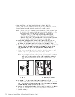
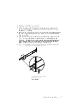
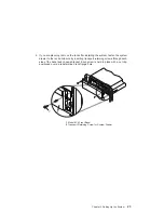
a. Align the black and white strip located on each side of the rack-mounting
template with the EIA locations on each side of the rack. Each black or white
section on the template is equal to 1 EIA. Each EIA consists of 3 holes.
b. Remove the protective coating from each adhesive strip located on the back of
the rack-mounting template. Lightly press the template into position on the
rack. Ensure that both the left and right side are at corresponding EIA
locations.
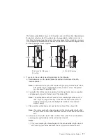
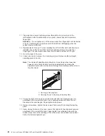
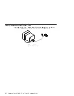
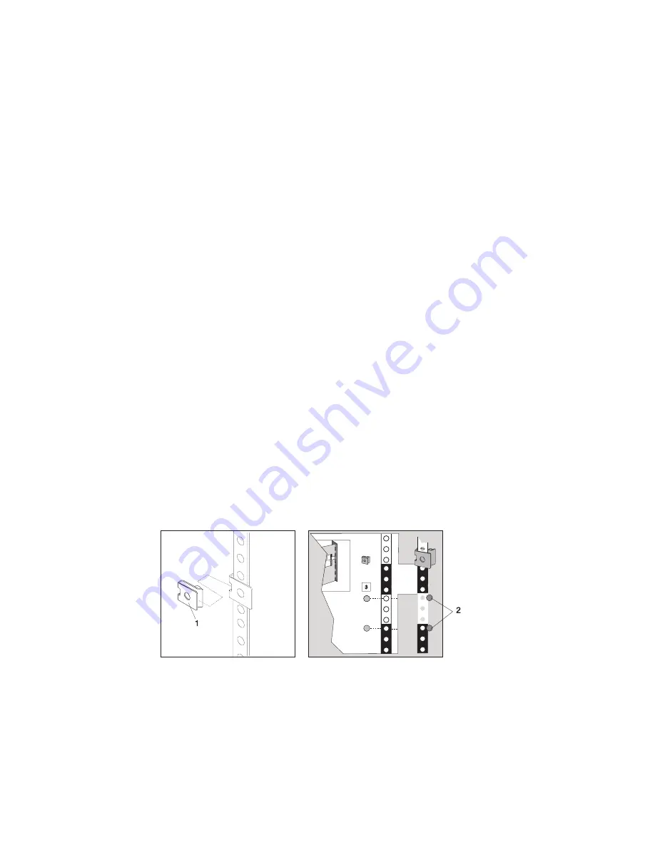
c. Install the nut clips into the holes as indicated by the template. The nut clips
aid in securing your system drawer to the rack while in transit.
Note: Anytime a populated rack is being moved, your system drawers should
be secured with two retaining thumbscrews threaded through the nut
clips. This secures the system front bezel and system chassis to the
rack.
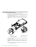
1 Nut Clip
2 Adhesive Dot Placement
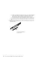
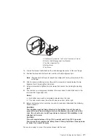
d. Locate the 4 dots, two printed on each side of the template. Put a
self-adhesive dot directly across from the templates printed dots on or near the
rack’s EIA strip. You will be using these dots to aid in correctly positioning the
rail alignment pins located on the front of each rail.
e. Remove the rack-mounting template from the front of the rack. You should now
have placed on the front of your rack 2 nut clips and 4 self-adhesive dots.
f. Continue to step 5.
16
Eserver
pSeries 630 Model 6C4 and Model 6E4 Installation Guide
Summary of Contents for @Server pSeries 630 6C4
Page 1: ...pSeries 630 Model 6C4 and Model 6E4 Installation Guide SA38 0605 01 ERserver IBM...
Page 2: ......
Page 3: ...pSeries 630 Model 6C4 and Model 6E4 Installation Guide SA38 0605 01 ERserver IBM...
Page 12: ...x Eserver pSeries 630 Model 6C4 and Model 6E4 Installation Guide...
Page 14: ...xii Eserver pSeries 630 Model 6C4 and Model 6E4 Installation Guide...
Page 22: ...6 Eserver pSeries 630 Model 6C4 and Model 6E4 Installation Guide...
Page 64: ...48 Eserver pSeries 630 Model 6C4 and Model 6E4 Installation Guide...
Page 148: ...132 Eserver pSeries 630 Model 6C4 and Model 6E4 Installation Guide...
Page 152: ...136 Eserver pSeries 630 Model 6C4 and Model 6E4 Installation Guide...
Page 156: ...140 Eserver pSeries 630 Model 6C4 and Model 6E4 Installation Guide...
Page 166: ...150 Eserver pSeries 630 Model 6C4 and Model 6E4 Installation Guide...
Page 179: ......
Page 180: ...IBMR Part Number 00P3937 Printed in U S A August 2002 SA38 0605 01 1P P N 00P3937...


