


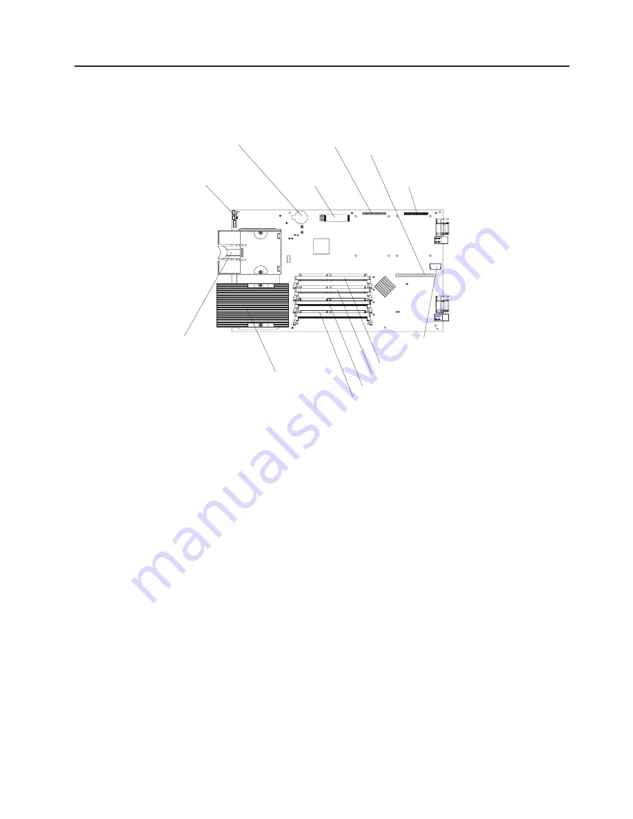
System board illustration
The following illustration shows the location of the system-board components,
including connectors for user-installable options.
Battery
SCSI expansion
connector (J8)
IDE connector 1
(J13)
IDE connector 2
(J62)
I/O expansion
option connector (J34)
I/O expansion
option connector (J9)
Control panel
connector (J64)
Microprocessor
socket 2
and heat sink filler
(U70)
Microprocessor 1
and heat sink (U66)
DIMM socket 1 (J1)
DIMM socket 2 (J5)
DIMM socket 3 (J2)
DIMM socket 4 (J6)
Note:
The SCSI expansion connector (J8) requires a terminator unless an
expansion option is connected to it.
Chapter 1. Introduction
9
Summary of Contents for BladeCanter HS20
Page 3: ...BladeCenter HS20 Type 8832 Installation and User s Guide ERserver...
Page 7: ...Japanese Voluntary Control Council for Interference VCCI statement 83 Index 85 Contents v...
Page 8: ...vi BladeCenter HS20 Type 8832 Installation and User s Guide...
Page 14: ...xii BladeCenter HS20 Type 8832 Installation and User s Guide...
Page 26: ...12 BladeCenter HS20 Type 8832 Installation and User s Guide...
Page 32: ...18 BladeCenter HS20 Type 8832 Installation and User s Guide...
Page 58: ...44 BladeCenter HS20 Type 8832 Installation and User s Guide...
Page 66: ...52 BladeCenter HS20 Type 8832 Installation and User s Guide...
Page 68: ...54 BladeCenter HS20 Type 8832 Installation and User s Guide...
Page 98: ...84 BladeCenter HS20 Type 8832 Installation and User s Guide...
Page 102: ...88 BladeCenter HS20 Type 8832 Installation and User s Guide...
Page 103: ......
Page 104: ...Part Number 59P6556 Printed in U S A 1P P N 59P6556...


