


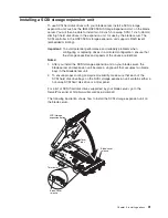


Complete the following steps to install the SCSI storage expansion unit:
1. Review the information in “Safety” beginning on page vii and “Installation
guidelines” on page 19.
2. Shut down the operating system, turn off the blade server, and remove the
blade server from the BladeCenter unit (see “Removing the blade server from
the BladeCenter unit” on page 20 for instructions).
3. Carefully lay the blade server on a flat, non-conductive surface.
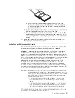
4. Remove the blade server cover.
a. Open the blade server cover (see “Opening the blade server cover” on
page 21 for instructions) and lift it off the blade server.
b. Store the cover in a safe place.
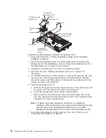
5. Locate the SCSI connector on the system board and remove the terminator
from the connector.
6. Install the SCSI storage expansion unit:
a. Orient the storage expansion unit as shown in the illustration.
b. Lower the storage expansion unit so that the slots at the rear slide down
onto the pins at the rear of the blade server.
c. Pivot the storage expansion unit closed and press it firmly into place until
the cover-release latches click. The connector on the expansion unit
automatically aligns with and plugs into the SCSI expansion connector (J8)
on the system board.
7. Insert the combined blade server and expansion unit into two adjacent
BladeCenter unit bays.
Note:
When any blade server or option is in blade bays 7 through 14, power
modules must be present in power bays 1 and 2,
and
power modules
must be present in power bays 3 and 4.
8. Turn on the blade server.
9. If you have not already done so, install the LSI device drivers for your operating
system. LSI device drivers are on the
Resource
CD that comes with the
BladeCenter unit. You can also get the latest version of the drivers from the IBM
Support Web site at http://www.ibm.com/pc/support/.
With the storage expansion unit installed on your blade server, you can install up to
two hot-swap SCSI hard disk drives in the option and configure them for embedded
mirroring (RAID level1). Each SCSI device must have a unique SCSI ID. This ID
enables the SCSI controller in the I/O expansion card to identify the device and
ensure that different devices on the same SCSI channel do not attempt to transfer
data simultaneously. The SCSI IDs for the hard disk drives in the expansion unit are
permanent (not configurable). Table 2 lists the SCSI IDs for the hard disk drives that
are installed in the expansion unit. See “Installing a SCSI hot-swap hard disk drive”
on page 33 for instructions for installing hard disk drives.
Table 2. SCSI IDs for hot-swap hard disk drives in the expansion unit
Device
SCSI ID
Drive bay 1
0
Drive bay 2
1
Note:
SCSI ID 7 is usually reserved for the SCSI controller; however, this SCSI ID
is changeable through the ServeRAID
™
configuration program or the LSI
configuration program utility.
32
BladeCenter HS20 Type 8832: Installation and User’s Guide
Summary of Contents for BladeCanter HS20
Page 3: ...BladeCenter HS20 Type 8832 Installation and User s Guide ERserver...
Page 7: ...Japanese Voluntary Control Council for Interference VCCI statement 83 Index 85 Contents v...
Page 8: ...vi BladeCenter HS20 Type 8832 Installation and User s Guide...
Page 14: ...xii BladeCenter HS20 Type 8832 Installation and User s Guide...
Page 26: ...12 BladeCenter HS20 Type 8832 Installation and User s Guide...
Page 32: ...18 BladeCenter HS20 Type 8832 Installation and User s Guide...
Page 58: ...44 BladeCenter HS20 Type 8832 Installation and User s Guide...
Page 66: ...52 BladeCenter HS20 Type 8832 Installation and User s Guide...
Page 68: ...54 BladeCenter HS20 Type 8832 Installation and User s Guide...
Page 98: ...84 BladeCenter HS20 Type 8832 Installation and User s Guide...
Page 102: ...88 BladeCenter HS20 Type 8832 Installation and User s Guide...
Page 103: ......
Page 104: ...Part Number 59P6556 Printed in U S A 1P P N 59P6556...


