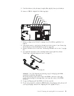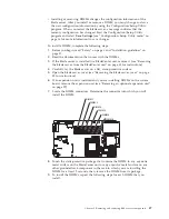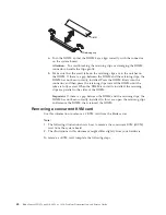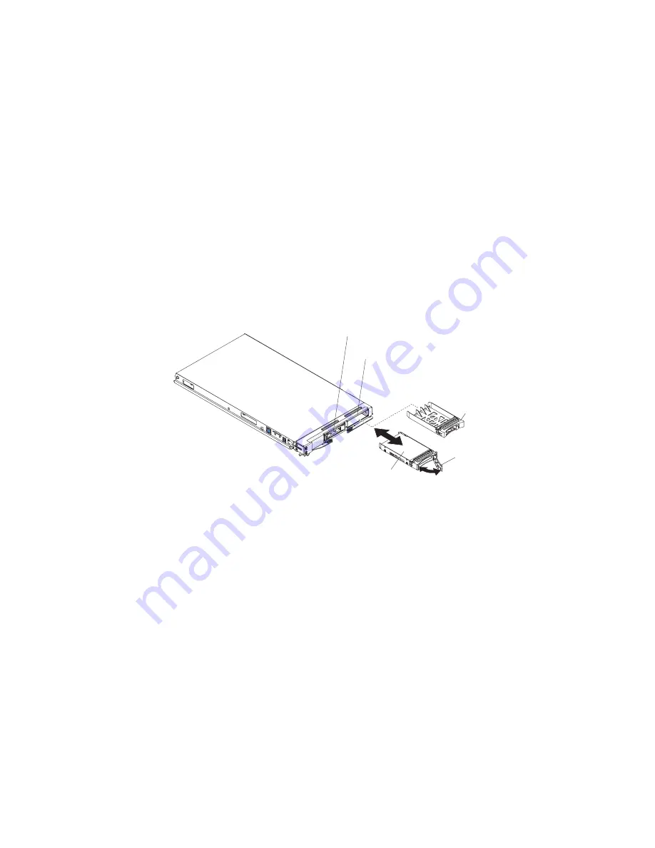
Installing a hot-swap storage drive
Use this information to install a hot-swap storage drive in the blade server.
To install a hot-swap storage drive, complete the following steps. The blade server
(machine type 8028) has two storage bays for installing or removing hot-swap
storage devices, such as SAS storage drives.
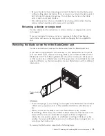
Note:
1.
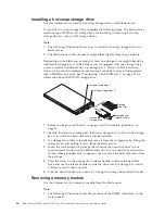
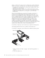
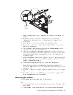
The following illustration shows how to install a hot-swap storage drive in a
blade server.
2.
The illustrations in this document might differ slightly from your hardware.
Depending on the blade server model, at least one storage drive might already be
installed in storage bay 0. If the blade server is equipped with one storage drive,
you can install an additional drive in storage bay 1. These two SAS hard disk
drives can be used to implement and manage a redundant array of independent
disks (RAID) level-1 array. See “Configuring a SAS RAID array” on page 22 for
information about SAS RAID configuration.
Hot-swap
storage drive
Storage
drive filler
Storage drive
release handle
Hot-swap storage bay 1
Hot-swap storage bay 0
1.
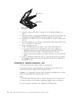
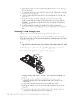
Before you begin, read “Safety” on page v and “Installation guidelines” on
page 31.
2.
Identify the hot-swap storage bay (hot-swap storage bay 0 or hot-swap storage
bay 1) in which the hard disk drive will be installed.
3.
If a storage-drive filler is installed, remove it from the storage bay by lifting the
release levers and pulling it away from the blade server.
4.
Touch the static-protective package that contains the hard disk drive to any
unpainted
metal surface on the BladeCenter unit or any
unpainted
metal surface
on any other grounded rack component; then, remove the hard disk drive from
the package.
5.
Press the arrow on the storage drive release handle to release the hard disk
drive and use the release handle to slide the drive into the storage bay until it
is firmly seated in the connector.
6.
Lock the hard disk drive into place by closing the storage drive release handle.
Removing a memory module
Use this information to a memory module from the blade server.
Note:
1.
The following illustration shows the locations of the DIMM connectors on the
system board.
44
BladeCenter HS12 Type 8014, 8028 or 1916: Problem Determination and Service Guide
Summary of Contents for BladeCenter HS12 Type 1916
Page 1: ...BladeCenter HS12 Type 8014 8028 or 1916 Problem Determination and Service Guide...
Page 2: ......
Page 3: ...BladeCenter HS12 Type 8014 8028 or 1916 Problem Determination and Service Guide...
Page 36: ...24 BladeCenter HS12 Type 8014 8028 or 1916 Problem Determination and Service Guide...
Page 186: ...174 BladeCenter HS12 Type 8014 8028 or 1916 Problem Determination and Service Guide...
Page 190: ...178 BladeCenter HS12 Type 8014 8028 or 1916 Problem Determination and Service Guide...
Page 198: ...186 BladeCenter HS12 Type 8014 8028 or 1916 Problem Determination and Service Guide...
Page 203: ......
Page 204: ...Part Number 60Y1601 Printed in USA 1P P N 60Y1601...


