v
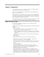
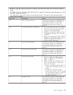
Follow the suggested actions in the order in which they are listed in the Action column until the problem is
solved.
v
See Chapter 4, “Parts listing, Types 8014, 8028 and 1916,” on page 25 to determine which components are CRUs
and which components are FRUs.
v
If an action step is preceded by “(Trained service technician only),” that step must be performed only by a
trained service technician.
Beep code
Description
Action
1-3-2
First 64K RAM parity test failed.
1.
Reseat the DIMMs. See “Removing a
memory module” on page 44 and
“Installing a memory module” on page 46.
2.
Replace the following components one at a
time, in the order shown, restarting the
blade server each time:
a.
DIMMs - See “Removing a memory
module” on page 44 and “Installing a
memory module” on page 46.
b.
(Trained service technician only)
System-board assembly - See “Removing
the system-board assembly” on page 65
and “Installing the system-board
assembly” on page 66.
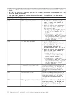
2-1-1
Secondary DMA register test failed.
(Trained service technician only) Replace the
system-board assembly. See “Removing the
system-board assembly” on page 65 and
“Installing the system-board assembly” on
page 66..
2-1-2
Primary DMA register test failed.
(Trained service technician only) Replace the
system-board assembly. See “Removing the
system-board assembly” on page 65 and
“Installing the system-board assembly” on
page 66.
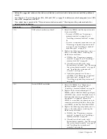
2-1-3
Primary interrupt mask register test
failed.
(Trained service technician only) Replace the
system-board assembly. See “Removing the
system-board assembly” on page 65 and
“Installing the system-board assembly” on
page 66.
2-1-4
Secondary interrupt mask register test
failed.
(Trained service technician only) Replace the
system-board assembly. See “Removing the
system-board assembly” on page 65 and
“Installing the system-board assembly” on
page 66.
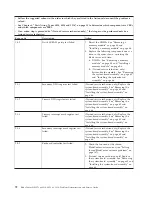
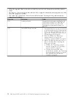
2-2-2
Keyboard controller test failed.
1.
Check the function of the shared
BladeCenter unit resources (see “Solving
shared BladeCenter resource problems” on
page 167).
2.
(Trained service technician only) Replace
the system-board assembly. See “Removing
the system-board assembly” on page 65 and
“Installing the system-board assembly” on
page 66.
72
BladeCenter HS12 Type 8014, 8028 or 1916: Problem Determination and Service Guide
Summary of Contents for BladeCenter HS12 Type 1916
Page 1: ...BladeCenter HS12 Type 8014 8028 or 1916 Problem Determination and Service Guide...
Page 2: ......
Page 3: ...BladeCenter HS12 Type 8014 8028 or 1916 Problem Determination and Service Guide...
Page 36: ...24 BladeCenter HS12 Type 8014 8028 or 1916 Problem Determination and Service Guide...
Page 186: ...174 BladeCenter HS12 Type 8014 8028 or 1916 Problem Determination and Service Guide...
Page 190: ...178 BladeCenter HS12 Type 8014 8028 or 1916 Problem Determination and Service Guide...
Page 198: ...186 BladeCenter HS12 Type 8014 8028 or 1916 Problem Determination and Service Guide...
Page 203: ......
Page 204: ...Part Number 60Y1601 Printed in USA 1P P N 60Y1601...


