v
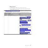
See Chapter 4, “Parts listing, Types 7871 and 1949,” on page 41 to determine which components are CRUs and
which components are FRUs.
v
If an action step is preceded by “(Trained service technician only),” that step must be performed only by a
trained service technician.
Error code
Description
Action
166-906-xxx
Failed the IMM I2C test due to a failure in the
memory configuration bus.
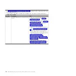
1.
Turn off the blade server, open the blade server
release levers and pull the blade server away
from the blade server bay, but do not remove it
from the bay. See “Removing the blade server
from the BladeCenter unit” on page 52 for more
information.
2.
Wait 45 seconds and reseat the blade server in
the blade module bay and turn on the blade
server. See “Installing the blade server in a
BladeCenter unit” on page 53 and “Turning on
the blade server” on page 13.
3.
Rerun the test. See “Diagnostic tools overview”
on page 97.
4.
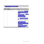
Make sure that the DSA Diagnostic code is
up-to-date, upgrade if necessary; then, rerun the
test. The latest code can be found on the IBM
support Web site at http://www.ibm.com/
support/docview.wss?uid=psg1SERV-DSA.
5.
Make sure that the IMM firmware level is
up-to-date, upgrade if necessary; then, rerun the
test. The installed firmware level can be found
in the DSA Diagnostic Event Log within the
Firmware/VPD section for this component. The
latest level firmware for this component can be
found on the IBM support Web site at
http://www.ibm.com/support/
docview.wss?uid=psg1MIGR-4JTS2T.
6.
Turn off the blade server, open the blade server
release levers and pull the blade server away
from the blade server bay, but do not remove it
from the bay. See “Removing the blade server
from the BladeCenter unit” on page 52 for more
information.
7.
Wait 45 seconds and reseat the blade server in
the blade module bay and turn on the blade
server. See “Installing the blade server in a
BladeCenter unit” on page 53 and “Turning on
the blade server” on page 13.
8.
Rerun the test. See “Diagnostic tools overview”
on page 97.
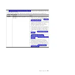
9.
(Trained service technician) If the failure
remains, replace the system-board (see
“Removing the system-board assembly” on page
94 and “Installing the system-board assembly”
on page 95).
Chapter 6. Diagnostics
199
Summary of Contents for BladeCenter HS22V 7871
Page 1: ...BladeCenter HS22V Type 7871 and 1949 Problem Determination and Service Guide...
Page 2: ......
Page 3: ...BladeCenter HS22V Type 7871 and 1949 Problem Determination and Service Guide...
Page 16: ...xiv BladeCenter HS22V Type 7871 and 1949 Problem Determination and Service Guide...
Page 20: ...4 BladeCenter HS22V Type 7871 and 1949 Problem Determination and Service Guide...
Page 34: ...18 BladeCenter HS22V Type 7871 and 1949 Problem Determination and Service Guide...
Page 64: ...48 BladeCenter HS22V Type 7871 and 1949 Problem Determination and Service Guide...
Page 112: ...96 BladeCenter HS22V Type 7871 and 1949 Problem Determination and Service Guide...
Page 240: ...224 BladeCenter HS22V Type 7871 and 1949 Problem Determination and Service Guide...
Page 244: ...228 BladeCenter HS22V Type 7871 and 1949 Problem Determination and Service Guide...
Page 252: ...236 BladeCenter HS22V Type 7871 and 1949 Problem Determination and Service Guide...
Page 257: ......
Page 258: ...Part Number 00Y8038 Printed in USA 1P P N 00Y8038...


