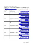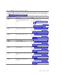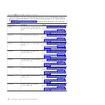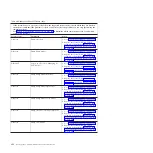
Table 19. CA000000 to CA2799FF checkpoints (continued)
v
If the system hangs on a progress code, follow the suggested actions in the order in which they are listed in
the Action column until the problem is solved. If an action solves the problem, you can stop performing the
remaining actions.
v
See Chapter 3, “Parts listing, Type 7998,” on page 235 to determine which components are CRUs and which
components are FRUs.
Progress code
Description
Action
CA00E199
The system is rebooting to enact changes
that were specified in the boot image
ELF header
1.
Verify that:
v
The bootp server is correctly configured;
then, retry the operation.
v
The network connections are correct;
then, retry the operation.
2.
If the problem persists:
a.
Go to “Checkout procedure” on page
186.
b.
Replace the system-board and chassis
assembly, as described in “Replacing the
Tier 2 system-board and chassis
assembly” on page 274.
CA00E19A
NVRAM auto-boot? variable not found -
assume FALSE
1.
Go to “Checkout procedure” on page 186.
2.
Replace the system-board and chassis
assembly, as described in “Replacing the
Tier 2 system-board and chassis assembly”
on page 274.
CA00E19B
NVRAM menu? variable not found -
assume FALSE
1.
Go to “Checkout procedure” on page 186.
2.
Replace the system-board and chassis
assembly, as described in “Replacing the
Tier 2 system-board and chassis assembly”
on page 274.
CA00E19D
Create NVRAM node
1.
Go to “Checkout procedure” on page 186.
2.
Replace the system-board and chassis
assembly, as described in “Replacing the
Tier 2 system-board and chassis assembly”
on page 274.
CA00E1A0
User requested boot to SMS menus
using keyboard entry
1.
Go to “Checkout procedure” on page 186.
2.
Replace the system-board and chassis
assembly, as described in “Replacing the
Tier 2 system-board and chassis assembly”
on page 274.
CA00E1A1
User requested boot to open firmware
prompt using keyboard entry
1.
Go to “Checkout procedure” on page 186.
2.
Replace the system-board and chassis
assembly, as described in “Replacing the
Tier 2 system-board and chassis assembly”
on page 274.
CA00E1A2
User requested boot using default
service mode boot list using keyboard
entry
1.
Go to “Checkout procedure” on page 186.
2.
Replace the system-board and chassis
assembly, as described in “Replacing the
Tier 2 system-board and chassis assembly”
on page 274.
Chapter 2. Diagnostics
121
Summary of Contents for BladeCenter JS12
Page 1: ...BladeCenter JS12 Type 7998 Problem Determination and Service Guide...
Page 2: ......
Page 3: ...BladeCenter JS12 Type 7998 Problem Determination and Service Guide...
Page 14: ...xii JS12 Type 7998 Problem Determination and Service Guide...
Page 248: ...234 JS12 Type 7998 Problem Determination and Service Guide...
Page 252: ...238 JS12 Type 7998 Problem Determination and Service Guide...
Page 290: ...276 JS12 Type 7998 Problem Determination and Service Guide...
Page 298: ...284 JS12 Type 7998 Problem Determination and Service Guide...
Page 302: ...288 JS12 Type 7998 Problem Determination and Service Guide...
Page 312: ...298 JS12 Type 7998 Problem Determination and Service Guide...
Page 317: ......
Page 318: ...Part Number 60Y1568 Printed in USA 1P P N 60Y1568...


