v
Follow the suggested actions in the order in which they are listed in the Action column until the problem is
solved.
v
See Chapter 3, “Parts listing, Type 7998,” on page 235 to determine which components are CRUs and which
components are FRUs.
v
If an action step is preceded by “(Trained service technician only),” that step must be performed only by a
trained service technician.
Isolation
Procedure Code
Symptom
Action
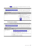
FSPSP54
A processor
over-temperature has
been detected. Check
for any
environmental issues
before replacing any
parts.
1.
Measure the ambient room temperature to see if it is in within the
upper limit of the normal operating range. The upper limit is less
than 35 degrees C or 95 degrees F. If the temperature exceeds this
limit, you must bring down the room temperature until it is within
the limit. When the temperature is within range, retry the operation.
2.
If the temperature is within the acceptable range, check the front and
rear of the BladeCenter unit to verify that the each is free of
obstructions that would impede the airflow. If there are obstructions,
you must clear the obstructions. Also clean the air inlets and exits in
the BladeCenter unit drawer as required. If you cleared obstructions,
retry the operation.
3.
Verify that the fans in the BladeCenter unit are working correctly. If
not, replace fans that are not turning or that are turning slowly. If
you replace fans, wait for the unit to cool and retry the operation.
4.
If the fans are functioning correctly, there are environmental issues
with the cooling of the processor. Replace the system board and
chassis assembly, as described in “Replacing the Tier 2 system-board
and chassis assembly” on page 274.
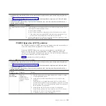
FSPSP55
An error has been
detected on a bus
between two FRUs.
The end-point FRUs
have been called out,
however, the source
of the error could be
the bus path between
the FRUs.
The bus error is corrected by the customer replaceable units (CRUs)
called out after this procedure. Replace the CRUs called out after this
procedure. See Chapter 4, “Removing and replacing blade server
components,” on page 239 for more information.
IOHUB Symbolic
CRU
The failing
component is the
RIO/HSL NIC on the
IPL path.
Replace the system board and chassis assembly, as described in
“Replacing the Tier 2 system-board and chassis assembly” on page 274.
IOBRDG
Symbolic CRU
The failing
component is the
RIO/HSL I/O bridge
on the IPL path.
Replace the system board and chassis assembly, as described in
“Replacing the Tier 2 system-board and chassis assembly” on page 274.
MEMBRD
Symbolic CRU
The failing
component is the
board the memory
DIMMs plug into.
Replace the system board and chassis assembly, as described in
“Replacing the Tier 2 system-board and chassis assembly” on page 274.
MEMCTLR
Symbolic CRU
The failing
component is one of
the memory
controllers.
Replace the system board and chassis assembly, as described in
“Replacing the Tier 2 system-board and chassis assembly” on page 274.
Chapter 2. Diagnostics
215
Summary of Contents for BladeCenter JS12
Page 1: ...BladeCenter JS12 Type 7998 Problem Determination and Service Guide...
Page 2: ......
Page 3: ...BladeCenter JS12 Type 7998 Problem Determination and Service Guide...
Page 14: ...xii JS12 Type 7998 Problem Determination and Service Guide...
Page 248: ...234 JS12 Type 7998 Problem Determination and Service Guide...
Page 252: ...238 JS12 Type 7998 Problem Determination and Service Guide...
Page 290: ...276 JS12 Type 7998 Problem Determination and Service Guide...
Page 298: ...284 JS12 Type 7998 Problem Determination and Service Guide...
Page 302: ...288 JS12 Type 7998 Problem Determination and Service Guide...
Page 312: ...298 JS12 Type 7998 Problem Determination and Service Guide...
Page 317: ......
Page 318: ...Part Number 60Y1568 Printed in USA 1P P N 60Y1568...

