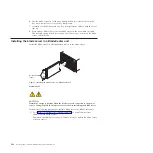
Installing the bezel assembly
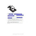
Install the bezel assembly.
1.
Connect the control-panel cable to the control-panel connector on the system
board.
2.
Carefully slide the bezel assembly onto the blade server until it clicks into
place.
3.
Install and close the blade server cover. See “Installing and closing the blade
server cover” on page 245.
Statement 21
CAUTION:
Hazardous energy is present when the blade server is connected to the power
source. Always replace the blade server cover before installing the blade
server.
4.
Install the blade server into the BladeCenter unit. See “Installing the blade
server in a BladeCenter unit” on page 242.
Control-panel
cable
Control-panel
connector
Bezel-assembly
release
Bezel
assembly
Bezel-assembly
release
Figure 11. Installing the bezel assembly
Chapter 4. Removing and replacing blade server components
247
Summary of Contents for BladeCenter JS12
Page 1: ...BladeCenter JS12 Type 7998 Problem Determination and Service Guide...
Page 2: ......
Page 3: ...BladeCenter JS12 Type 7998 Problem Determination and Service Guide...
Page 14: ...xii JS12 Type 7998 Problem Determination and Service Guide...
Page 248: ...234 JS12 Type 7998 Problem Determination and Service Guide...
Page 252: ...238 JS12 Type 7998 Problem Determination and Service Guide...
Page 290: ...276 JS12 Type 7998 Problem Determination and Service Guide...
Page 298: ...284 JS12 Type 7998 Problem Determination and Service Guide...
Page 302: ...288 JS12 Type 7998 Problem Determination and Service Guide...
Page 312: ...298 JS12 Type 7998 Problem Determination and Service Guide...
Page 317: ......
Page 318: ...Part Number 60Y1568 Printed in USA 1P P N 60Y1568...


