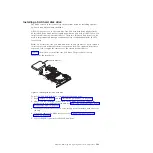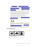
Table 33 shows the sequence for installing DIMMs.
Table 33. Installing a memory module
Pair
DIMM connectors
First
Second
Third
Fourth
See “Supported DIMMs” on page 4 for additional information about the type of
memory that is compatible with the blade server, and the rules that control which
sizes and speeds you can use in the blade server. Figure 15 shows how to open the
retaining clip to install the memory module.
To install a DIMM, complete the following steps:
1.
Read “Safety” on page v and the “Installation guidelines” on page 239.
2.
Read the documentation that comes with the DIMMs.
3.
Shut down the operating system, turn off the blade server, and remove the
blade server from the BladeCenter unit. See “Removing the blade server from
a BladeCenter unit” on page 241.
4.
Carefully lay the blade server on a flat, static-protective surface, with the
cover side up.
5.
Open and remove the blade server cover. See “Removing the blade server
cover” on page 244.
6.
Locate the DIMM connectors on the system board. See the illustration in
“System-board connectors” on page 9. Determine the connector into which
you will install the DIMM.
7.
Touch the static-protective package that contains the part to any
unpainted
metal surface on the BladeCenter unit or any
unpainted
metal surface on any
other grounded rack component; then, remove the part from its package.
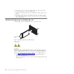
DIMM
Retaining clip
Figure 15. Installing a memory module
252
JS12 Type 7998: Problem Determination and Service Guide
Summary of Contents for BladeCenter JS12
Page 1: ...BladeCenter JS12 Type 7998 Problem Determination and Service Guide...
Page 2: ......
Page 3: ...BladeCenter JS12 Type 7998 Problem Determination and Service Guide...
Page 14: ...xii JS12 Type 7998 Problem Determination and Service Guide...
Page 248: ...234 JS12 Type 7998 Problem Determination and Service Guide...
Page 252: ...238 JS12 Type 7998 Problem Determination and Service Guide...
Page 290: ...276 JS12 Type 7998 Problem Determination and Service Guide...
Page 298: ...284 JS12 Type 7998 Problem Determination and Service Guide...
Page 302: ...288 JS12 Type 7998 Problem Determination and Service Guide...
Page 312: ...298 JS12 Type 7998 Problem Determination and Service Guide...
Page 317: ......
Page 318: ...Part Number 60Y1568 Printed in USA 1P P N 60Y1568...


