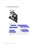
Replacing the Tier 2 system-board and chassis assembly
You can install this Tier 2 CRU yourself or request IBM to install it, at no
additional charge, under the type of warranty service that is designated for the
blade server. Replace the system board and chassis assembly. When replacing the
system board, you will replace the system board, blade base (chassis),
microprocessors, and heat sinks as one assembly. After replacement, you must
either update the system with the latest firmware or restore the pre-existing
firmware that the customer provides on a diskette or CD image.
Note:
See “System-board layouts” on page 8 for more information on the locations
of the connectors and LEDs on the system board.
Perform the following procedure to replace the system-board and chassis assembly.
1.
Read “Safety” on page v and the “Installation guidelines” on page 237.
2.
Shut down the operating system, turn off the blade server, and remove the
blade server from the BladeCenter unit. See “Removing the blade server from
a BladeCenter unit” on page 239.
3.
Carefully lay the blade server on a flat, static-protective surface, with the
cover side up.
4.
Open and remove the blade server cover. See “Removing the blade server
cover” on page 242.
5.
Remove the blade server bezel assembly. See “Removing the bezel assembly”
on page 244.
6.
Remove any of the installed components listed below from the system board;
then, place them on a non-conductive surface or install them on the new
system board and chassis assembly.
v
I/O expansion card. See “Removing and installing an I/O expansion card”
on page 256.
v
Hard disk drives. See “Removing the SAS hard disk drive” on page 246.
v
DIMMs. See “Removing a memory module” on page 248.
v
Management card. See “Removing the management card” on page 250.
v
Battery. See “Removing the battery” on page 263.
7.
Touch the static-protective package that contains the system-board and chassis
assembly to any
unpainted
metal surface on the BladeCenter unit or any
unpainted
metal surface on any other grounded rack component; then, remove
the assembly from its package.
8.
Install any of the components listed below that were removed from the old
system-board and chassis assembly.
v
I/O expansion card. See “Removing and installing an I/O expansion card”
on page 256.
v
Hard disk drives. See “Installing the SAS hard disk drive” on page 247.
v
DIMMs. See “Installing a memory module” on page 249.
v
Management card. See “Installing the management card” on page 252.
v
Battery. See “Installing the battery” on page 264.
270
JS22 Type 7998: Problem Determination and Service Guide
Summary of Contents for BladeCenter JS22
Page 1: ...BladeCenter JS22 Type 7998 Problem Determination and Service Guide...
Page 2: ......
Page 3: ...BladeCenter JS22 Type 7998 Problem Determination and Service Guide...
Page 14: ...xii JS22 Type 7998 Problem Determination and Service Guide...
Page 248: ...234 JS22 Type 7998 Problem Determination and Service Guide...
Page 286: ...272 JS22 Type 7998 Problem Determination and Service Guide...
Page 294: ...280 JS22 Type 7998 Problem Determination and Service Guide...
Page 298: ...284 JS22 Type 7998 Problem Determination and Service Guide...
Page 308: ...294 JS22 Type 7998 Problem Determination and Service Guide...
Page 313: ......
Page 314: ...Part Number 44W2359 Printed in USA 1P P N 44W2359...


