4.
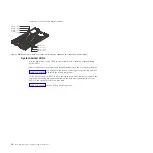
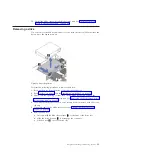
Press the blade-cover release (as shown by
1
for the base unit and by
2
for
the expansion unit in Figure 8 on page 26) on each side of the blade server,
rotate the cover on the cover pins (
3
) and lift the cover open.
5.
Lay the cover flat, or lift it from the cover pins on the blade server and store
the cover for future use.
Statement 21
CAUTION:
Hazardous energy is present when the blade server is connected to the power
source. Always replace the blade server cover before installing the blade
server.
Removing the expansion unit
Remove the expansion unit to operate the JS43 blade server as a JS23 single-width
blade server.
1.
Read “Safety” on page v and the “Installation guidelines” on page 23.
2.
Shut down the operating system, turn off the blade server, and remove the
blade server from the BladeCenter unit. See “Removing the blade server from
a BladeCenter unit” on page 25.
3.
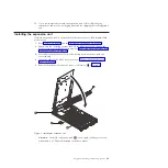
Carefully lay the blade server on a flat, static-protective surface, with the
cover side up.
4.
Open and remove the blade server cover. See “Removing the blade server
cover” on page 26.
5.
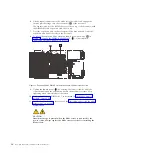
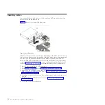
To access the expansion blade retention thumb screw (shown by
4
in
Figure 9), remove the DIMM in DIMM slot 1 (
5
), as described in “Removing
5
4
Figure 9. Expansion blade DIMM 1 slot and the expansion blade retention screw
Chapter 3. Installing and removing options
27
Summary of Contents for BladeCenter JS23
Page 3: ...BladeCenter JS23 and BladeCenter JS43 Type 7778 Installation and User s Guide ...
Page 6: ...iv JS23 JS43 Type 7778 Installation and User s Guide ...
Page 24: ...12 JS23 JS43 Type 7778 Installation and User s Guide ...
Page 86: ...74 JS23 JS43 Type 7778 Installation and User s Guide ...
Page 87: ......
Page 88: ... Part Number 44R5338 Printed in USA 1P P N 44R5338 ...


