background image

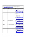
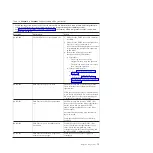
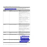
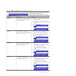
Table 18. BA000010 to BA400002 Partition firmware SRCs (continued)

v

Follow the suggested actions in the order in which they are listed in the Action column until the problem is
solved. If an action solves the problem, then you can stop performing the remaining actions.

v

See Chapter 3, “Parts listing, type 7891,” on page 225 to determine which components are CRUs and which
components are FRUs.

Error code

Description

Action

BA153003

Gigabit Ethernet adapter failure

1.

Check for server firmware updates; then,
install the updates if available.

2.

Replace the Gigabit Ethernet adapter.

BA154010

HEA software error

1.

Go to “Checkout procedure” on page 176.

2.

Replace the system-board, as described in
“Replacing the FRU system-board and
chassis assembly” on page 264.

BA154020

The required open firmware property
was not found.

1.

Reboot the blade server.

2.

If the problem persists:

a.

Go to “Checkout procedure” on page
176.

b.

Replace the system-board, as described
in “Replacing the FRU system-board
and chassis assembly” on page 264.

BA154030

Invalid parameters were passed to the
HEA device driver.

1.

Reboot the blade server.

2.

If the problem persists:

a.

Go to “Checkout procedure” on page
176.

b.

Replace the system-board, as described
in “Replacing the FRU system-board
and chassis assembly” on page 264.

BA154040

The TFTP package open failed

1.

Reboot the blade server.

2.

If the problem persists:

a.

Go to “Checkout procedure” on page
176.

b.

Replace the system-board, as described
in “Replacing the FRU system-board
and chassis assembly” on page 264.

BA154050

The transmit operation failed.

1.

Reboot the blade server.

2.

If the problem persists:

a.

Go to “Checkout procedure” on page
176.

b.

Replace the system-board, as described
in “Replacing the FRU system-board
and chassis assembly” on page 264.

BA154060

Failed to initialize the HEA port or
queue

1.

Reboot the blade server.

2.

If the problem persists:

a.

Go to “Checkout procedure” on page
176.

b.

Replace the system-board, as described
in “Replacing the FRU system-board
and chassis assembly” on page 264.

84

Power Systems: Problem Determination and Service Guide for the IBM PS703 (7891-73X) and PS704 (7891-74X)

Summary of Contents for BladeCenter PS703

Page 1: ...Power Systems Problem Determination and Service Guide for the IBM PS703 7891 73X and PS704 7891 74X GI11 9841 00...

Page 2: ......

Page 3: ...Power Systems Problem Determination and Service Guide for the IBM PS703 7891 73X and PS704 7891 74X GI11 9841 00...

Page 4: ...ty Notices manual G229 9054 and the IBM Environmental Notices and User Guide Z125 5823 This edition applies to IBM Power Systems servers that contain the POWER7 processor and to all associated models...

Page 5: ...edure 177 Verifying the partition configuration 179 Running the diagnostics program 179 Starting AIX concurrent diagnostics 179 Starting stand alone diagnostics from a CD 179 Starting stand alone diag...

Page 6: ...a combination form factor expansion card 257 Removing the battery 258 Installing the battery 258 Removing the disk drive tray 260 Installing the disk drive tray 261 Removing the tier 2 management card...

Page 7: ...the publications package shipped with the product The booklet contains the safety information in your national language with references to the U S English source Before using a U S English publicatio...

Page 8: ...to this product to properly wired outlets v When possible use one hand only to connect or disconnect signal cables v Never turn on any equipment when there is evidence of fire water or structural dama...

Page 9: ...e customer to ensure that the outlet is correctly wired and grounded to prevent an electrical shock CAUTION v Do not install a unit in a rack where the internal rack ambient temperatures will exceed t...

Page 10: ...the loaded rack cabinet Refer to the documentation that comes with your rack cabinet for the weight of a loaded rack cabinet v Verify that all door openings are at least 760 x 230 mm 30 x 80 in v Ens...

Page 11: ...This product might contain one or more of the following devices CD ROM drive DVD ROM drive DVD RAM drive or laser module which are Class 1 laser products Note the following information v Do not remove...

Page 12: ...ollowing v Network telecommunications facilities v Locations where the NEC National Electrical Code applies The intrabuilding ports of this equipment are suitable for connection to intrabuilding or un...

Page 13: ...the warranty and getting service and assistance see the information center or the Warranty and Support Information document on the IBM BladeCenter Documentation CD Related documentation Documentation...

Page 14: ...ention These notices indicate potential damage to programs devices or data An attention notice is placed just before the instruction or situation in which damage might occur v Caution These statements...

Page 15: ...ses USB 2 0 on base system board for communication with removable media drives v Optical media available by shared chassis feature Environment v Air temperature Blade server with power on 10 35 C 50 9...

Page 16: ...essor support group 1 4 5 8 9 12 13 16 must be the same size and speed v Install only supported DIMMs as described on the ServerProven website See http www 03 ibm com servers eserver serverproven comp...

Page 17: ...18 3 19 4 20 5 21 6 22 7 23 8 24 9 25 10 26 11 27 12 28 13 29 14 30 15 31 16 32 2 X X 4 X X X X 6 X X X X X X 8 X X X X X X X X 10 X X X X X X X X X X 12 X X X X X X X X X X X X 14 X X X X X X X X X...

Page 18: ...se the management module to determine whether local control has been disabled on the blade server Note The operating system in the blade server must provide USB support for the blade server to recogni...

Page 19: ...ation LED When this blue LED is lit it has been turned on by the system administrator to aid in visually locating the blade server The location LED can be turned off through the Web interface of the m...

Page 20: ...n the blade server behind the control panel door See Blade server control panel buttons and LEDs on page 6 for the location Note The power control LED can remain on solidly for up to 1 minute after yo...

Page 21: ...3 blade server connectors 1 Operator panel connector 2 DIMM connectors See Figure 7 on page 11 for individual connectors 3 3 V lithium battery connector P1 E1 4 Management card connector P1 C17 5 2 5...

Page 22: ...attery connector P1 E1 5 Management card connector 6 2 5 SAS HDD P1 D1 or 1 8 SATA SSD P1 C18 P1 C18 D1 P1 C18 D2 carrier 7 CIOv expansion card connector P1 C19 8 High speed CFFh expansion card connec...

Page 23: ...C20 Figure 7 shows individual DIMM connectors for the PS703 system board Figure 8 shows individual DIMM connectors for the PS704 system board The numbers in parentheses are for the PS704 expansion un...

Page 24: ...e expansion unit and push the blue button on the base unit system board to view LEDs on the system board of the base unit The following figure shows LEDs on the PS703 blade server The following figure...

Page 25: ...4 System board LED 5 DRV1 LED HDD or SSD1 6 DRV2 LED SSD2 7 SSD carrier LED 8 CIOv LED 9 CFFh LED 10 DIMM error LEDs 11 Check card below LED 12 Light path LED 13 System board LED 14 DVR1 LED HDD or SS...

Page 26: ...14 Power Systems Problem Determination and Service Guide for the IBM PS703 7891 73X and PS704 7891 74X...

Page 27: ...es and system buses IBM hardware error checkers have these distinct attributes v Continuous monitoring of system operations to detect potential calculation errors v Attempted isolation of physical fau...

Page 28: ...tables Use the troubleshooting tables to find solutions to problems that have identifiable symptoms See Troubleshooting tables on page 183 v Dump data collection In some circumstances an error might r...

Page 29: ...processor attempts to dump data that is necessary to analyze the error from appropriate parts of the system Note If you power off the blade through the management module while the service processor i...

Page 30: ...M 16 Un P1 C16 Yes 2 5 SAS disk drive Un P1 D1 Yes Management card Un P1 C17 Yes Solid state drive carrier Un P1 C18 Yes Solid state drive 1 top drive Un P1 C18 D1 Yes Solid state drive 2 bottom drive...

Page 31: ...1 C13 Yes DIMM 14 Un P1 C14 Yes DIMM 15 Un P1 C15 Yes DIMM 16 Un P1 C16 Yes 2 5 SAS disk drive Un P1 D1 Yes Management card Un P1 C17 Yes Solid state drive carrier Un P1 C18 Yes Solid state drive 1 to...

Page 32: ...CFFh expansion card Un P2 C20 Yes CIOv form factor expansion card Un P2 C19 Yes Ethernet port 0 Un P2 T3 No Ethernet port 1 Un P2 T4 No Integrated SAS controller Un P2 T5 No Machine location code Utt...

Page 33: ...ght also be included See Error logs on page 176 for information about viewing the management module event log Service request numbers can be viewed using the AIX diagnostics CD or various operating sy...

Page 34: ...ntion required Service processor v AAxxxxxx Attention required Partition firmware v B1xxxxxx Service processor error such as a boot problem v B6xxxxxx Licensed Internal Code or hardware event error v...

Page 35: ...the following a If the location code reported with this SRC is Un P2 replace the expansion system board assembly as described in Removing the expansion unit for a PS704 blade server on page 237 b If t...

Page 36: ...ving the expansion unit for a PS704 blade server on page 237 b If the location code reported with this SRC is Un P1 replace the base system board and chassis assembly as described in Replacing the FRU...

Page 37: ...assembly as described in Removing the expansion unit for a PS704 blade server on page 237 b If the location code reported with this SRC is Un P1 replace the base system board and chassis assembly as d...

Page 38: ...moving the expansion unit for a PS704 blade server on page 237 b If the location code reported with this SRC is Un P1 replace the base system board and chassis assembly as described in Replacing the F...

Page 39: ...e expansion unit for a PS704 blade server on page 237 b If the location code reported with this SRC is Un P1 replace the base system board and chassis assembly as described in Replacing the FRU system...

Page 40: ...to Checkout procedure on page 176 2 Replace the expansion system board Un P2 assembly as described in Removing the expansion unit for a PS704 blade server on page 237 2675 1 1 Reg_CPU0_P5IO2C_Vio_pGoo...

Page 41: ...following a If the location code reported with this SRC is Un P2 replace the expansion system board assembly as described in Removing the expansion unit for a PS704 blade server on page 237 b If the l...

Page 42: ...page 193 267C REG_P5IO2C_core 1 2V pGood fault 1 Go to Checkout procedure on page 176 2 Perform one of the following a If the location code reported with this SRC is Un P2 replace the expansion system...

Page 43: ...llowing one at a time until the failure is no longer detected 1 The SSD interposer card Un P2 C18 2 The first SSD drive Un P2 C18 D1 3 The second SSD drive Un P2 C18 D2 2911 SSD interposer card pGood...

Page 44: ...Replacing the FRU system board and chassis assembly on page 264 The DTRCARD symbolic CRU isolation procedure is in Service processor problems on page 193 8400 Invalid configuration decode 1 Check for...

Page 45: ...447 SSD interposer card pGood fault Replace the interposer card on the base system planar Un P1 C18 8480 Bad or missing memory controller VID 1 Go to Checkout procedure on page 176 2 Perform one of th...

Page 46: ...le reading a virtual optical volume Resolve any errors on the Network File System server 632BCFC6 The file specified does not contain data that can be processed as a virtual optical volume On the Netw...

Page 47: ...rted clean the disk and attempt the failing operation again 3 If the operation fails again with the same system reference code ask your media source for a replacement disk 632CC400 Physical link error...

Page 48: ...is required A2D03002 User initiated RSCDUMP of IBM i partition s SLIC bootloader and PFW content No corrective action is required A700yyyy Licensed internal code SRCs An A700xxxx system reference code...

Page 49: ...es a suggested action to correct the problem Table 15 AA00E1A8 to AA260005 Partition firmware attention codes v Follow the suggested actions in the order in which they are listed in the Action column...

Page 50: ...e server 2 If the problem remains go to Boot problem resolution on page 182 AA06000C The media in a device in the boot list was not bootable 1 Replace the media in the device with known good media or...

Page 51: ...es then install the updates if available and retry the operation AA170210 Setenv setenv parameter error the name contains a null character 1 Go to Checkout procedure on page 176 2 Replace the system b...

Page 52: ...em then you can stop performing the remaining actions v See Chapter 3 Parts listing type 7891 on page 225 to determine which components are CRUs and which components are FRUs Reference Code Descriptio...

Page 53: ...on of a partition did not complete Check for server firmware updates then install the updates if available B2001144 A problem occurred during the migration of a partition The migration of a partition...

Page 54: ...Correct the startup settings B2001266 The partition could not start up You are attempting to start up an operating system that is not supported Install a supported operating system and restart the pa...

Page 55: ...e updates then install the updates if available B2002260 During the startup of a partition the partition firmware attempted an operation that failed Go to Isolating firmware problems on page 216 B2002...

Page 56: ...m occurred during the startup of a partition Look for other errors and resolve them B2003120 Informational system log entry only No corrective action is required B2003123 Informational system log entr...

Page 57: ...n page 216 B2005114 A problem occurred during the startup of a partition There is not enough space to contain the partition main storage dump The startup will not continue Go to Isolating firmware pro...

Page 58: ...mp Check for server firmware updates then install the updates if available B200514A A Firmware Assisted Dump did not complete due to a copy error Check for server firmware updates then install the upd...

Page 59: ...tempt to continue Look for other errors and resolve them B200690A During the startup of a partition an error occurred while copying open firmware into the partition load area Go to Isolating firmware...

Page 60: ...updates then install the updates if available B2008121 During the startup of a partition the partition did not start up due to a system firmware error Go to Isolating firmware problems on page 216 B2...

Page 61: ...200A140 A lower priority partition lost a usable processor to supply it to a higher priority partition with a bad processor Evaluate the entire LPAR configuration Adjust partition profiles with the ne...

Page 62: ...only No corrective action is required B200F00B Informational system log entry only No corrective action is required B200F00C Informational system log entry only No corrective action is required B200F...

Page 63: ...No immediate action is necessary Continue running the system normally At the earliest convenient time or service window work with IBM Support to collect a platform dump and restart the system then go...

Page 64: ...is assembly as described in Replacing the FRU system board and chassis assembly on page 264 0803 Informational system log entry only No corrective action is required 0804 Informational system log entr...

Page 65: ...settings that you intend to preserve The service processor reboots after IBM Support resets the server firmware settings If the problem persists Replace the system board as described in Replacing the...

Page 66: ...16 5122 An error occurred during a search for the load source If the partition fails to startup go to Isolating firmware problems on page 216 Otherwise no corrective action is required 5123 Informatio...

Page 67: ...n error Replace the system board and chassis assembly as described in Replacing the FRU system board and chassis assembly on page 264 54DD Informational system log entry only No corrective action is r...

Page 68: ...o Isolating firmware problems on page 216 6951 An error occurred because a partition needed more NVRAM than was available Use the Integrated Virtualization Manager IVM to delete one or more partitions...

Page 69: ...rective action is required 697C Connection from service processor to system processor failed Replace the system board and chassis assembly as described in Replacing the FRU system board and chassis as...

Page 70: ...and info logs 2 Replace the system board and chassis assembly as described in Replacing the FRU system board and chassis assembly on page 264 Send the failed FRU and the data to IBM for fault analysi...

Page 71: ...persists replace the system board and chassis assembly as described in Replacing the FRU system board and chassis assembly on page 264 Send the failed FRU and the data to IBM for fault analysis 6A28 P...

Page 72: ...ating firmware problems on page 216 F103 System firmware failure 1 Collect the event log information 2 Collect the platform dump information 3 Go to Isolating firmware problems on page 216 F104 Operat...

Page 73: ...leting the suggested actions see Checkout procedure on page 176 and Solving undetermined problems on page 223 Table 18 BA000010 to BA400002 Partition firmware SRCs v Follow the suggested actions in th...

Page 74: ...firmware failed to exchange virtual continuation events 1 Reboot the blade server 2 If the problem persists a Go to Checkout procedure on page 176 b Replace the system board as described in Replacing...

Page 75: ...A000081 Failed to get the firmware license policy 1 Reboot the blade server 2 If the problem persists a Go to Checkout procedure on page 176 b Replace the system board as described in Replacing the FR...

Page 76: ...bed in Replacing the FRU system board and chassis assembly on page 264 BA00E860 Failure when initializing sensors 1 Go to Checkout procedure on page 176 2 Replace the system board as described in Repl...

Page 77: ...e FRU system board and chassis assembly on page 264 BA010004 Bootp failed Perform the following actions that checkpoint CA00E174 describes 1 Verify that v The bootp server is correctly configured then...

Page 78: ...y that all of the iSCSI configuration arguments on the operating system comply with the configuration for the iSCSI Host Bus Adapter HBA which is the iSCSI initiator BA01000A The itname parameter stri...

Page 79: ...the maximum length allowed The embedded host Ethernet adapters HEAs help provide iSCSI which is supported by iSCSI software device drivers on either AIX or Linux Verify that all of the iSCSI configura...

Page 80: ...em board and chassis assembly on page 264 BA012011 TCP failed to read from the network 1 Reboot the blade server 2 If the problem persists a Go to Checkout procedure on page 176 b Replace the system b...

Page 81: ...bootp server is correctly configured then retry the operation v The network connections are correct then retry the operation 2 If the problem persists a Go to Checkout procedure on page 176 b Replace...

Page 82: ...tion 2 If the problem persists a Go to Checkout procedure on page 176 b Replace the system board as described in Replacing the FRU system board and chassis assembly on page 264 BA01D001 Opening the DH...

Page 83: ...page 176 2 Replace the system board as described in Replacing the FRU system board and chassis assembly on page 264 BA01D050 DHCP discover no good offer DHCP discovery did not receive any DHCP offers...

Page 84: ...that the DHCP server is functioning properly BA01D055 DHCP discover DHCP decline DHCP discovery did receive a DHCP offer from one or more servers that meet the client requirements However the client...

Page 85: ...nd model are not recognized by the blade server firmware 1 Reboot the blade server 2 If the problem persists a Go to Checkout procedure on page 176 b Replace the system board as described in Replacing...

Page 86: ...n page 176 2 Replace the system board as described in Replacing the FRU system board and chassis assembly on page 264 BA060008 No configurable adapters found by the Remote IPL menu in the SMS utilitie...

Page 87: ...rating system that supports shared processors 2 Disable logical partitioning with shared processors in the operating system 3 If the problem remains a Go to Checkout procedure on page 176 b Replace th...

Page 88: ...menus set the boot list to the default boot list 2 Shut down then start up the blade server 3 Use SMS menus to customize the boot list as required 4 If the problem persists a Go to Checkout procedure...

Page 89: ...FRU system board and chassis assembly on page 264 BA090004 SCSD DASD send diagnostic failed devofl cmd 1 Go to Checkout procedure on page 176 2 Replace the system board as described in Replacing the...

Page 90: ...ssembly on page 264 BA09000F Media is not present 1 Insert new media with the correct format 2 If the problem persists a Go to Checkout procedure on page 176 b Replace the system board as described in...

Page 91: ...on page 176 2 Replace the system board as described in Replacing the FRU system board and chassis assembly on page 264 BA120001 On an undetermined SCSD device test unit ready failed hardware error 1...

Page 92: ...eshoot the SCSD devices 2 Verify that the SCSD cables and devices are properly plugged Correct any problems that are found 3 Replace the SCSD cables and devices 4 If the problem persists a Go to Check...

Page 93: ...s described in Replacing the FRU system board and chassis assembly on page 264 BA130012 USB CD ROM in the media tray execution of ATA ATAPI command failed 1 Retry the operation 2 Reboot the blade serv...

Page 94: ...ve the CD or DVD in the drive and replace it with a known good disk 2 If the problem persists a Retry the operation b Reboot the blade server c Troubleshoot the media tray and CD ROM drive d Replace t...

Page 95: ...s that are found 3 Replace the SCSD cables and devices 4 If the problem persists a Go to Checkout procedure on page 176 b Replace the system board as described in Replacing the FRU system board and ch...

Page 96: ...ng the FRU system board and chassis assembly on page 264 BA154030 Invalid parameters were passed to the HEA device driver 1 Reboot the blade server 2 If the problem persists a Go to Checkout procedure...

Page 97: ...page 176 b Replace the system board as described in Replacing the FRU system board and chassis assembly on page 264 BA170201 The firmware was unable to expand target partition saving configuration var...

Page 98: ...installation BA170998 NVRAMRC script evaluation error command line execution error 1 Go to Checkout procedure on page 176 2 Replace the system board as described in Replacing the FRU system board and...

Page 99: ...heckout procedure on page 176 b Replace the system board as described in Replacing the FRU system board and chassis assembly on page 264 BA180099 PCI probe error bridge in freeze state slot in reset s...

Page 100: ...ce 1 Reboot the blade server 2 If the problem persists a Go to Checkout procedure on page 176 b Replace the system board as described in Replacing the FRU system board and chassis assembly on page 264...

Page 101: ...6 b Replace the system board as described in Replacing the FRU system board and chassis assembly on page 264 BA210010 The transfer of control to the SLIC loader failed 1 Go to Checkout procedure on pa...

Page 102: ...2 If the problem persists a Go to Checkout procedure on page 176 b Replace the system board as described in Replacing the FRU system board and chassis assembly on page 264 BA210101 The partition firm...

Page 103: ...or EEH related errors in the event log 2 Resolve any EEH event log entries that are found 3 Correct any errors that are found and reboot the blade server 4 If the problem persists a Go to Checkout pro...

Page 104: ...chassis assembly on page 264 BA280000 RTAS discovered an invalid operation that may cause a hardware error 1 Go to Checkout procedure on page 176 2 Replace the system board as described in Replacing...

Page 105: ...as described in Replacing the FRU system board and chassis assembly on page 264 BA330000 Memory allocation error 1 Reboot the blade server 2 If the problem persists a Go to Checkout procedure on page...

Page 106: ...eCenter open fabric manager location code mapping data from the service processor 1 Reboot the blade server 2 If the problem persists a Go to Checkout procedure on page 176 b Replace the system board...

Page 107: ...on page 264 BA340008 An internal firmware error occurred the open fabric manager system initiator capability data version was not correct 1 Reboot the blade server 2 If the problem persists a Go to Ch...

Page 108: ...21 A logical partition event communication failure occurred when writing the BladeCenter open fabric manager system initiator capabilities data to the service processor 1 Reboot the blade server 2 If...

Page 109: ...component when there is a hang condition Notes 1 For checkpoints with no associated location code see Light path diagnostics on page 210 to identify the failing component when there is a hang conditio...

Page 110: ...page 176 2 Replace the system board as described in Replacing the FRU system board and chassis assembly on page 264 C1001F0D Pre standby discovery completed in initial transition file While the blade...

Page 111: ...s 1 Go to Checkout procedure on page 176 2 Replace the system board as described in Replacing the FRU system board and chassis assembly on page 264 C1009x10 Hardware object manager HOM initialize HOM...

Page 112: ...d as described in Replacing the FRU system board and chassis assembly on page 264 C1009x38 Processor check ring IPL step in progress 1 Go to Checkout procedure on page 176 2 Replace the system board a...

Page 113: ...ce the system board as described in Replacing the FRU system board and chassis assembly on page 264 C1009x54 Start processor clocks IPL step in progress 1 Go to Checkout procedure on page 176 2 Replac...

Page 114: ...ure on page 176 2 Replace the system board as described in Replacing the FRU system board and chassis assembly on page 264 C1009x74 ASIC mask attentions being set up 1 Go to Checkout procedure on page...

Page 115: ...Replace the system board as described in Replacing the FRU system board and chassis assembly on page 264 C1009x94 ASIC transmit receive initialization step in progress 1 Go to Checkout procedure on p...

Page 116: ...s described in Replacing the FRU system board and chassis assembly on page 264 C1009xB8 ASIC memory diagnostic step in progress 1 Go to Checkout procedure on page 176 2 Replace the system board as des...

Page 117: ...rvisor code modules are being transferred to system storage 1 Go to Checkout procedure on page 176 2 Replace the system board as described in Replacing the FRU system board and chassis assembly on pag...

Page 118: ...ontinues the IPL The virtual service processor can start a variety of operating systems Some codes are specific to an operating system and therefore do not apply to all operating systems Table 21 list...

Page 119: ...on page 217 2 Replace the system board as described in Replacing the FRU system board and chassis assembly on page 264 C20012FF Partition startup is allowed to proceed 1 Go to Recovering the system fi...

Page 120: ...described in Replacing the FRU system board and chassis assembly on page 264 C200211F Power on command successful 1 Go to Recovering the system firmware on page 217 2 Replace the system board as descr...

Page 121: ...217 2 Replace the system board as described in Replacing the FRU system board and chassis assembly on page 264 C20024FF End powering on slots 1 Go to Recovering the system firmware on page 217 2 Repl...

Page 122: ...Replacing the FRU system board and chassis assembly on page 264 C20031FF Waiting for ISL command completion 1 Go to Recovering the system firmware on page 217 2 Replace the system board as described...

Page 123: ...place the system board as described in Replacing the FRU system board and chassis assembly on page 264 C20043FF Load source device is connected 1 Go to Recovering the system firmware on page 217 2 Rep...

Page 124: ...Replacing the FRU system board and chassis assembly on page 264 C2006060 Waiting for LID load to complete 1 Go to Recovering the system firmware on page 217 2 Replace the system board as described in...

Page 125: ...Replace the system board as described in Replacing the FRU system board and chassis assembly on page 264 C20080FF Hypervisor low level session manager object is ready 1 Go to Recovering the system fi...

Page 126: ...assis assembly on page 264 C200813F End associate of system ports 1 Go to Recovering the system firmware on page 217 2 Replace the system board as described in Replacing the FRU system board and chass...

Page 127: ...he order in which they are listed in the Action column until the problem is solved If an action solves the problem you can stop performing the remaining actions v See Chapter 3 Parts listing type 7891...

Page 128: ...o to Checkout procedure on page 176 2 Replace the system board as described in Replacing the FRU system board and chassis assembly on page 264 CA000032 Attempting to register lpevent queues 1 Go to Ch...

Page 129: ...y on page 264 CA000091 Attempting to load the second pass of C code 1 Go to Checkout procedure on page 176 2 Replace the system board as described in Replacing the FRU system board and chassis assembl...

Page 130: ...page 264 CA00D011 First pass open firmware initialization complete control returned to initialization firmware 1 Go to Checkout procedure on page 176 2 Replace the system board as described in Replac...

Page 131: ...Checkout procedure on page 176 2 Replace the system board as described in Replacing the FRU system board and chassis assembly on page 264 CA00E110 Create KDUMP properties 1 Reboot the blade server 2 I...

Page 132: ...the system board as described in Replacing the FRU system board and chassis assembly on page 264 CA00E139 Create aliases node and system aliases 1 Go to Checkout procedure on page 176 2 Replace the sy...

Page 133: ...being set from the management module bootlist 1 Reboot the blade server 2 If the problem persists a Go to Checkout procedure on page 176 b Replace the system board as described in Replacing the FRU sy...

Page 134: ...to Checkout procedure on page 176 2 Replace the system board as described in Replacing the FRU system board and chassis assembly on page 264 CA00E15B Transfer control to operating system service mode...

Page 135: ...er is correctly configured then retry the operation v The network connections are correct then retry the operation 2 If the problem persists a Go to Checkout procedure on page 176 b Replace the system...

Page 136: ...to enact changes that were specified in ibm client architecture support Go to Boot problem resolution on page 182 CA00E199 The system is rebooting to enact changes that were specified in the boot imag...

Page 137: ...try 1 Go to Checkout procedure on page 176 2 Replace the system board as described in Replacing the FRU system board and chassis assembly on page 264 CA00E1A4 User requested boot to SMS menus 1 Go to...

Page 138: ...ce the system board as described in Replacing the FRU system board and chassis assembly on page 264 CA00E1B1 System booting system directed boot device repair 1 Go to Checkout procedure on page 176 2...

Page 139: ...the system board as described in Replacing the FRU system board and chassis assembly on page 264 CA00E1DD A graphics adapter has been selected as the firmware console but the USB keyboard is not atta...

Page 140: ...ce list for fibre channel adapters The location code of the SAN adapter being scanned is also displayed 1 Go to Checkout procedure on page 176 2 Replace the system board as described in Replacing the...

Page 141: ...chassis assembly on page 264 CA00E443 Generate NVRAM configuration variable dictionary words 1 Go to Checkout procedure on page 176 2 Replace the system board as described in Replacing the FRU system...

Page 142: ...system board as described in Replacing the FRU system board and chassis assembly on page 264 CA00E860 Initializing sensors 1 Go to Checkout procedure on page 176 2 Replace the system board as describe...

Page 143: ...Initialize gdata for activate_firmware 1 Go to Checkout procedure on page 176 2 Replace the system board as described in Replacing the FRU system board and chassis assembly on page 264 CA00E890 Starti...

Page 144: ...ve the problem 3 Retry the firmware update 4 If the problem persists a Go to Checkout procedure on page 176 b Replace the system board as described in Replacing the FRU system board and chassis assemb...

Page 145: ...Restart the blade server using the permanent boot image as described in Starting the PERM image on page 217 3 Use the Update and Manage System Flash menu to reject the temporary image D1001xxx to D1xx...

Page 146: ...ed in Replacing the FRU system board and chassis assembly on page 264 D1031xxx Dump dump header fips header 1 Go to Checkout procedure on page 176 2 Replace the system board as described in Replacing...

Page 147: ...tem board as described in Replacing the FRU system board and chassis assembly on page 264 D1141xxx Dump code version 1 Go to Checkout procedure on page 176 2 Replace the system board as described in R...

Page 148: ...m board as described in Replacing the FRU system board and chassis assembly on page 264 D1231xxx Dump update dump headers 1 Go to Checkout procedure on page 176 2 Replace the system board as described...

Page 149: ...1 Go to Checkout procedure on page 176 2 Replace the system board as described in Replacing the FRU system board and chassis assembly on page 264 D12D1xxx Rmove core core app time pid 1 Go to Checkout...

Page 150: ...sequence 1 Go to Checkout procedure on page 176 2 Replace the system board as described in Replacing the FRU system board and chassis assembly on page 264 D13B1xxx Get dump length sequence 1 Go to Ch...

Page 151: ...hassis assembly on page 264 D1xx3y03 Get array values 1 Go to Checkout procedure on page 176 2 Replace the system board as described in Replacing the FRU system board and chassis assembly on page 264...

Page 152: ...n page 264 D1xx3y0C Get JTAG register 1 Go to Checkout procedure on page 176 2 Replace the system board as described in Replacing the FRU system board and chassis assembly on page 264 D1xx3y0D Stop cl...

Page 153: ...re on page 176 2 Replace the system board as described in Replacing the FRU system board and chassis assembly on page 264 D1xxB0FF Request to initiate power off program has been sent 1 Go to Checkout...

Page 154: ...lems on page 223 4 After replacing a component verify the replacement part and perform a log repair action using the AIX diagnostics 101 711 through FFC 725 SRNs AIX might generate service request num...

Page 155: ...e last three or four digits of the SRN following the dash 1 If your 110 SRN is not listed substitute the last three or four digits of the SRN for xxxx and go to Failing function codes on page 173 to i...

Page 156: ...scaded enclosures Go to Performing the checkout procedure on page 177 2506 4020 Configuration error connections exceed IOA design limits Go to Performing the checkout procedure on page 177 2506 4030 C...

Page 157: ...Disk Array Go to Performing the checkout procedure on page 177 2506 9022 Two or more disks are missing from a RAID 5 or RAID 6 Disk Array Go to Performing the checkout procedure on page 177 2506 9023...

Page 158: ...o Performing the checkout procedure on page 177 2506 9075 Incomplete multipath connection between controller and remote controller Go to Performing the checkout procedure on page 177 2506 9076 Missing...

Page 159: ...1 Check the BladeCenter management module event log If an error was recorded by the system see POST progress codes checkpoints on page 97 2 Replace any parts reported by the diagnostic program 3 Repl...

Page 160: ...OST progress codes checkpoints on page 97 2 Replace any parts reported by the diagnostic program 3 Replace the system board 254E 201 254E 221 Adapter configuration error Go to Performing the checkout...

Page 161: ...ure 1 Check the BladeCenter management module event log If an error was recorded by the system see POST progress codes checkpoints on page 97 2 Replace any parts reported by the diagnostic program 3 R...

Page 162: ...Configuration Register Test Failure for the Fibre Channel adapter card Go to Performing the checkout procedure on page 177 2604 203 2604 PCI Wrap Test Failure for the Fibre Channel adapter card Replac...

Page 163: ...07 221 Error on Read Write Operation for the Fibre Channel adapter card Go to Performing the checkout procedure on page 177 2607 701 2607 Error Log Analysis indicates that the adapter self test failed...

Page 164: ...rity error Replace the 4X PCI E DDR InfiniBand Host Channel Adapter 2624 705 2624 Error Log Analysis indicates that this adapter has failed due to a internal error Replace the 4X PCI E DDR InfiniBand...

Page 165: ...Command timeouts threshold exceeded Go to Performing the checkout procedure on page 177 2640 133 2640 Command timeout with error condition Go to Performing the checkout procedure on page 177 2640 134...

Page 166: ...ed by the diagnostic program 3 Replace the system board and chassis assembly as described in Replacing the Tier 2 system board and chassis assembly 268B 114 268B An unrecoverable hardware error 1 Chec...

Page 167: ...an error was recorded by the system see POST progress codes checkpoints on page 97 2 Replace any parts reported by the diagnostic program 3 Replace the system board and chassis assembly as described i...

Page 168: ...g If an error was recorded by the system see POST progress codes checkpoints on page 97 2 Replace any parts reported by the diagnostic program 3 Replace the system board and chassis assembly as descri...

Page 169: ...26B4 110 26B4 The media format is corrupted 26B4 112 26B4 The diagnostic test failed 26B4 114 26B4 An unrecoverable hardware error 26B4 116 26B4 26BD A protocol error Check the levels of the device a...

Page 170: ...D 252B 26B4 Error log analysis indicates poor signal quality 26B4 640 Error log analysis indicates a path error 26D2 102 26D2 An unrecoverable media error occurred 26D2 104 26D2 The motor failed to re...

Page 171: ...26D2 252B Unit attention condition has occurred on the Send Diagnostic command 26D2 138 26D2 Error log analysis indicates that the disk drive is operating at a higher than recommended temperature Chec...

Page 172: ...recorded by the system see POST progress codes checkpoints on page 97 2 Replace any parts reported by the diagnostic program 3 Replace the system board 2E10 603 2E10 Error Log Analysis indicates that...

Page 173: ...dition 1 Check the BladeCenter management module event log If an error was recorded by the system see POST progress codes checkpoints on page 97 2 Replace any parts reported by the diagnostic program...

Page 174: ...nagement module event log If an error was recorded by the system see POST progress codes checkpoints on page 97 2 Replace any parts reported by the diagnostic program 3 Replace the system board 2E14 6...

Page 175: ...on condition 1 Check the BladeCenter management module event log If an error was recorded by the system see POST progress codes checkpoints on page 97 2 Replace any parts reported by the diagnostic pr...

Page 176: ...nagement module event log If an error was recorded by the system see POST progress codes checkpoints on page 97 2 Replace any parts reported by the diagnostic program 3 Replace the system board 2E21 6...

Page 177: ...program 3 Replace the system board 2E23 103 2E23 Flash Test Failure 1 Check the BladeCenter management module event log If an error was recorded by the system see POST progress codes checkpoints on pa...

Page 178: ...the BladeCenter management module event log If an error was recorded by the system see POST progress codes checkpoints on page 97 2 Replace any parts reported by the diagnostic program 3 Replace the s...

Page 179: ...34 601 2E34 Download firmware error 1 Check the BladeCenter management module event log If an error was recorded by the system see POST progress codes checkpoints on page 97 2 Replace any parts report...

Page 180: ...y the diagnostic program 3 Replace the system board 2E36 602 2E36 EEPROM read error 1 Check the BladeCenter management module event log If an error was recorded by the system see POST progress codes c...

Page 181: ...system see POST progress codes checkpoints on page 97 2 Replace part numbers reported by the diagnostic program 3 If no entry is found Replace the system board A24 xxx Spurious interrupts have exceede...

Page 182: ...ssis assembly as described in Replacing the FRU system board and chassis assembly on page 264 ssss 108 ssss The bus test failed 1 Check the BladeCenter management module event log If an error was reco...

Page 183: ...ssembly on page 264 ssss 122 ssss A SCSD reservation conflict error 1 Check the BladeCenter management module event log If an error was recorded by the system see POST progress codes checkpoints on pa...

Page 184: ...r management module event log If an error was recorded by the system see POST progress codes checkpoints on page 97 2 Replace any parts reported by the diagnostic program 3 Replace the system board an...

Page 185: ...ss codes checkpoints on page 97 2 Replace any parts reported by the diagnostic program 3 Replace the system board and chassis assembly as described in Replacing the FRU system board and chassis assemb...

Page 186: ...d and chassis assembly System SP interface logic problem 2D5 System board and chassis assembly I2C primary 2D6 System board and chassis assembly I2C secondary 2D7 System board and chassis assembly VPD...

Page 187: ...em board and chassis assembly 25C4 Broadcom Ethernet adapter 2607 Emulex 8 Gb Fibre Channel expansion card CIOv 2624 4x InfiniBand DDR expansion card CFFh 2625 4x InfiniBand QDR expansion card CFFh 26...

Page 188: ...ure The checkout procedure is the sequence of tasks that you should follow to diagnose a problem in the blade server About the checkout procedure Review this information before performing the checkout...

Page 189: ...e codes SRCs on page 21 3 If the AIX operating system records a service request number SRN see Service request numbers SRNs on page 142 4 Check the BladeCenter management module event log If an error...

Page 190: ...s program on page 181 This ends the AIX procedure Step 007 Perform the following steps 1 Use the management module Web interface to make sure that the device from which you load the stand alone diagno...

Page 191: ...erating system prompt to start the diagnostics program and display its Function Selection menu See Using the diagnostics program on page 181 for more information about running the diagnostics program...

Page 192: ...NIM server client Also see the Configuring the NIM Master and Creating Basic Installation Resources Web page 1 Verify with the system administrator and systems users that the blade server can be shut...

Page 193: ...eps listed to perform one of the following tasks v Problem Determination a From the Function Selection menu select Diagnostic Routines and press Enter b From the Diagnostic Mode Selection menu select...

Page 194: ...not select your blade server from the list of servers and modify the boot sequence Cycle power on your blade server to retry the boot Note If Network is selected the blade server will try to boot fro...

Page 195: ...Running the diagnostics program on page 179 for information about testing the blade server If you have just added new software or a new optional device and the blade server is not working complete th...

Page 196: ...ostic test runs successfully replace the drive you removed with a new one Intermittent problems Identify intermittent problem symptoms and corrective actions v Follow the suggested actions in the orde...

Page 197: ...e suggested actions in the order in which they are listed in the Action column until the problem is solved v See Chapter 3 Parts listing type 7891 on page 225 to determine which components are CRUs an...

Page 198: ...the corrective actions to take v Follow the suggested actions in the order in which they are listed in the Action column until the problem is solved v See Chapter 3 Parts listing type 7891 on page 22...

Page 199: ...or more information Table 34 shows the procedure for isolating which PCI expansion card is failing Table 34 PCI expansion card problem isolation procedure v Follow the suggested actions in the order i...

Page 200: ...any other installed devices or cables 2 If the option comes with its own test instructions use those instructions to test the option 3 Reseat the device that you just installed 4 Replace the device t...

Page 201: ...interface to erify or the blade server was instructed through the management module Web interface to start 2 If you just installed a device in the blade server remove it and restart the blade server...

Page 202: ...by Trained service technician only that step must be performed only by a trained service technician Isolation Procedure Code Symptom Action LPARCFG Symbolic CRU There is a configuration problem with...

Page 203: ...dule 17 DIMM 2 or 18 Px C2 P1 C2 is memory module 2 P2 C2 is memory module 18 DIMM 3 or 19 Px C3 P1 C3 is memory module 3 P2 C3 is memory module 19 DIMM 4 or 20 Px C4 P1 C4 is memory module 4 P2 C4 is...

Page 204: ...r 31 Px C15 P1 C15 is memory module 15 P2 C15 is memory module 31 DIMM 16 or 32 Px C16 P1 C16 is memory module 16 P2 C16 is memory module 32 2 See Removing a memory module on page 249 for location inf...

Page 205: ...ocedure code is recorded in the management module event log A message with three procedures might be similar to the following example except that the entry would be on one line in the event log SN YL3...

Page 206: ...ts replace the system board and chassis assembly as described in Replacing the FRU system board and chassis assembly on page 264 CAPACTY Symbolic CRU The failing component is the management card 1 Rep...

Page 207: ...s replace the system board and chassis assembly as described in Replacing the FRU system board and chassis assembly on page 264 If the SRC is B1xxB107 or B1xxB108 The system has detected a problem wit...

Page 208: ...d in Replacing the FRU system board and chassis assembly on page 264 FSPSP05 The service processor has detected a problem in the platform firmware 1 Verify that the operating system is running If it i...

Page 209: ...Replace DIMMs 2 and 4 or DIMMs 18 and 20 DIMM 3 Px C3 Replace DIMMs 1 and 3 or DIMMs 17 and 19 DIMM 4 Px C4 Replace DIMMs 2 and 4 or DIMMs 18 and 20 DIMM 5 Px C5 Replace DIMMs 5 and 7 or DIMMs 21 and...

Page 210: ...ssis assembly on page 264 FSPSP14 The service processor cannot establish communication with the server firmware The server firmware will continue to run the system and partitions while it attempts to...

Page 211: ...assembly as described in Replacing the FRU system board and chassis assembly on page 264 FSPSP23 The system needs to perform a service processor dump 1 Save the service processor dump to storage by u...

Page 212: ...embly as described in Replacing the FRU system board and chassis assembly on page 264 FSPSP31 The service processor has detected that one or more of the required fields in the system VPD has not initi...

Page 213: ...tain the error To correct the error exchange the memory cards of the incorrect type with those of the correct type SRC B1xx C02B A group of memory cards are missing and are required so that other memo...

Page 214: ...and chassis assembly as described in Replacing the FRU system board and chassis assembly on page 264 FSPSP47 The system has detected an error within the PSI link Replace the system board and chassis a...

Page 215: ...lace DIMMs 1 and 3 for P2 C1 replace DIMMs 17 and 19 DIMM 2 Px C2 Replace DIMMs 2 and 4 or DIMMs 18 and 20 DIMM 3 Px C3 Replace DIMMs 1 and 3 or DIMMs 17 and 19 DIMM 4 Px C4 Replace DIMMs 2 and 4 or D...

Page 216: ...ge The upper limit is less than 35 degrees C or 95 degrees F If the temperature exceeds this limit you must bring down the room temperature until it is within the limit When the temperature is within...

Page 217: ...6 of the SRC is marked compatible in the blade center advanced management module AMM interface Click System Status I O Compatibility 3 If the I O module is marked as compatible continue with the next...

Page 218: ...I O bridge on the IPL path Replace the system board and chassis assembly as described in Replacing the FRU system board and chassis assembly on page 264 MEMBRD Symbolic CRU The failing component is t...

Page 219: ...P1 C2 is memory module 2 P2 C2 is memory module 18 DIMM 3 or 19 Px C3 P1 C3 is memory module 3 P2 C3 is memory module 19 DIMM 4 or 20 Px C4 P1 C4 is memory module 4 P2 C4 is memory module 20 DIMM 5 o...

Page 220: ...memory module 15 P2 C15 is memory module 31 DIMM 16 or 32 Px C16 P1 C16 is memory module 16 P2 C16 is memory module 32 2 See Removing a memory module on page 249 for location information and the remov...

Page 221: ...actions in the order in which they are listed in the Action column until the problem is solved v See Chapter 3 Parts listing type 7891 on page 225 to determine which components are CRUs and which comp...

Page 222: ...anel indicates an error use the descriptions of the LEDs to diagnose the problem and take corrective action LEDs are available for the following components v Battery base unit only v SAS disk drive on...

Page 223: ...ilable in the management module event log v If the blade error LED is lit it indicates that an error has occurred and you should proceed to the next step 2 If an error has occurred view the light path...

Page 224: ...e PS704 blade server Figure 13 LED locations on the base system board of the PS704 blade server Figure 14 LED locations on the board of the PS704 expansion unit 212 Power Systems Problem Determination...

Page 225: ...FRUs v If an action step is preceded by Trained service technician only that step must be performed only by a trained service technician Lit light path diagnostics LED Description Action None An error...

Page 226: ...DIMM 30 P2 C15 DIMM 31 P2 C16 DIMM 32 A memory error occurred 1 Verify that the DIMM indicated by the lit LED is a supported memory module as described on the ServerProven website 2 Reseat the DIMM i...

Page 227: ...es not correct the problem replace the solid state drive carrier See Removing an SSD carrier on page 244 CFFh expansion card error P1 C20 P2 C20 An I O expansion card option error occurred 1 Make sure...

Page 228: ...em board and chassis assembly error has occurred A microprocessor failure shows up as a system board and chassis assembly error 1 Replace the blade server cover reinsert the blade server in the BladeC...

Page 229: ...can force the blade server to start the PERM permanent image To force the blade server to start the PERM permanent image complete the following procedure 1 Access the Advanced Management Module menus...

Page 230: ...ays the current system firmware levels for the TEMP and PERM images This function also displays which image the blade server used to start up 1 Start the diagnostics program See Running the diagnostic...

Page 231: ...ocedures to help you isolate blade server problems from shared BladeCenter resource problems If the problem is thought to be with a shared resource see the online information center or the Problem Det...

Page 232: ...sing a USB hub make sure that the hub is operating correctly and that any software the hub requires is installed c Plug the USB device directly into the USB port bypassing the hub to check its operati...

Page 233: ...able if applicable c Removable media drive d Media tray 9 Verify that the management module is operating correctly See the online information center or the Problem Determination and Service Guide or t...

Page 234: ...online information or the Installation Guide for your management module for more information 10 Replace the management module See the online information center or the Problem Determination and Servic...

Page 235: ...he BladeCenter unit where the blade server is installed If the LEDs indicate that the power supplies are working correctly and reseating the blade server does not correct the problem complete the foll...

Page 236: ...configuration ever worked What changes if any were made before it failed Is this the original reported failure or has this failure been reported before v Diagnostic program type and version level v Ha...

Page 237: ...ting identifies each replaceable part and its part number Figure 15 shows replaceable components that are available for the PS703 and PS704 blade server Figure 15 Parts illustration type 7891 PS703 an...

Page 238: ...Expansion system board and chassis assembly v PS704 with two eight core POWER7 microprocessors 74Y3206 Various see Failing function codes on page 173 1 Cover 46C7341 2 3 Gb SAS pass through expansion...

Page 239: ...502 7 DIMM filler 60H2962 8 Management card v PS703 v PS704 v 74Y2681 v 74Y2681 9 Bezel assembly with control panel v PS703 v PS704 v 74Y6131 v 74Y6129 9 OEM bezel assembly with control panel 74Y6130...

Page 240: ...228 Power Systems Problem Determination and Service Guide for the IBM PS703 7891 73X and PS704 7891 74X...

Page 241: ...type model and operating system and then click Go Click the Download tab if necessary for device driver and firmware updates Note Changes are made periodically to the IBM website Procedures for locati...

Page 242: ...ent can cause static electricity to build up around you v Handle the device carefully holding it by its edges or its frame v Do not touch solder joints pins or exposed circuitry v Do not leave the dev...

Page 243: ...the Installation guidelines on page 229 2 If the blade server is operating shut down the operating system 3 Press the power control button behind the control panel door to turn off the blade server Se...

Page 244: ...ot done so already install any optional devices that you want such as a SAS drive or memory modules 4 Select the bay for the blade server v See the online information or the Installation and User s Gu...

Page 245: ...e BladeCenter unit bezel Important Do not place the label on the blade server or in any way block the ventilation holes on the blade server See the online information or the documentation that comes w...

Page 246: ...remove the blade server cover Figure 18 Removing the cover from a PS703 blade server Figure 19 Removing the cover from a PS704 blade server 234 Power Systems Problem Determination and Service Guide fo...

Page 247: ...ver pins 2 and lift the cover open 5 Lay the cover flat or lift it from the cover pins on the blade server and store the cover for future use Statement 21 CAUTION Hazardous energy is present when the...

Page 248: ...s 1 in Figure 20 on page 235 at the rear of the blade server Before you close the cover verify that all components are installed and seated correctly and that you have not left loose tools or parts in...

Page 249: ...move the blade server cover See Removing the blade server cover on page 233 Note If you are servicing the base unit of a PS704 blade server you must first remove the expansion unit For more informatio...

Page 250: ...ed to you Replacing the expansion unit in a PS704 blade server Install a new expansion unit on the PS704 double wide blade server You must have already completed the procedure Removing the expansion u...

Page 251: ...the expansion unit until it lies flat on the PS704 base unit 3 To access the expansion blade retention thumb screw see 4 in Figure 25 Figure 24 Replacing the expansion unit Figure 25 Expansion blade...

Page 252: ...lways replace the blade server cover before installing the blade server 7 Install the blade server into the BladeCenter unit See Installing the blade server in a BladeCenter unit on page 232 Removing...

Page 253: ...kaging instructions and use any packaging materials for shipping that are supplied to you Installing the bezel assembly You can install a bezel on a PS703 blade server or on either the base unit or th...

Page 254: ...e BladeCenter unit See Removing the blade server from a BladeCenter unit on page 231 4 Carefully lay the blade server on a flat static protective surface with the cover side up 5 Open and remove the b...

Page 255: ...stall a hard disk drive complete the following steps 1 Read the Safety topic and the Installation guidelines on page 229 2 Shut down the operating system turn off the blade server and remove the blade...

Page 256: ...ardous energy is present when the blade server is connected to the power source Always replace the blade server cover before installing the blade server 8 Install the blade server into the BladeCenter...

Page 257: ...sion unit for a PS704 blade server on page 237 6 Remove the drive a Pull and hold the blue release lever 1 at the front of the drive tray b Slide the carrier case forward 2 to disengage the connector...

Page 258: ...se See Installing an SSD on page 248 7 Place the carrier case 1 into the drive tray and push it toward the rear of the blade into the connector until the drive moves past the lever at the front of the...

Page 259: ...lade server cover on page 233 Note If you are servicing the base unit of a PS704 blade server you must first remove the expansion unit For more information see Removing the expansion unit for a PS704...

Page 260: ...e operating system turn off the blade server and remove the blade server from the BladeCenter unit See Removing the blade server from a BladeCenter unit on page 231 3 Carefully lay the blade server on...

Page 261: ...e Always replace the blade server cover before installing the blade server 10 Install the blade server into the BladeCenter unit See Installing the blade server in a BladeCenter unit on page 232 Remov...

Page 262: ...MM 16 in the PS703 server and DIMM 16 or DIMM 32 in the PS704 server and if a combination form factor horizontal card CFFh is present lift the blue cam mechanism so that you can maneuver your finger u...

Page 263: ...ts of DIMM modules for the PS704 blade server Table 38 Memory module combinations for the PS703 blade server DIMM count PS703 DIMM slots 1 2 3 4 5 6 7 8 9 10 11 12 13 14 15 16 2 X X 4 X X X X 6 X X X...

Page 264: ...ion that comes with the DIMMs 3 Shut down the operating system turn off the blade server and remove the blade server from the BladeCenter unit See Removing the blade server from a BladeCenter unit on...

Page 265: ...his card can become unseated when accessing DIMM 16 in the PS703 server and DIMM 16 or DIMM 32 in the PS704 server 12 Install and close the blade server cover See Installing and closing the blade serv...

Page 266: ...he blade server cover on page 233 Note If you are servicing the base unit of a PS704 blade server you must first remove the expansion unit For more information see Removing the expansion unit for a PS...

Page 267: ...information see Removing the expansion unit for a PS704 blade server on page 237 4 Touch the static protective package that contains the part to any unpainted metal surface on the BladeCenter unit or...

Page 268: ...the blade server cover See Removing the blade server cover on page 233 Note If you are servicing the base unit of a PS704 blade server you must first remove the expansion unit For more information see...

Page 269: ...on page 237 4 Remove the plastic cover for the PCI Express PCI e connector 1 5 Touch the static protective package that contains the part to any unpainted metal surface on the BladeCenter unit or any...

Page 270: ...BladeCenter unit on page 231 3 Carefully lay the blade server on a flat static protective surface with the cover side up 4 Open and remove the blade server cover See Removing the blade server cover o...

Page 271: ...gure any other blade server settings v To avoid possible danger read and follow the following safety statement Statement 2 CAUTION When replacing the lithium battery use only IBM Part Number 33F8354 o...

Page 272: ...ng the blade server 6 Install the blade server into the BladeCenter unit See Installing the blade server in a BladeCenter unit on page 232 7 Turn on the blade server and reset the system date and time...

Page 273: ...drive on page 242 6 Remove the four screws that secure the drive tray 1 in Figure 44 on page 260 to the system board and remove the drive tray Installing the disk drive tray You can install the disk...

Page 274: ...ve the blade server cover See Removing the blade server cover on page 233 Note If you are servicing the base unit of a PS704 blade server you must first remove the expansion unit For more information...

Page 275: ...and verify that the card is securely on the connector and pushed down all the way to the main board 5 Install and close the blade server cover See Installing and closing the blade server cover on pag...

Page 276: ...ge 233 Note If you are servicing the base unit of a PS704 blade server you must first remove the expansion unit For more information see Removing the expansion unit for a PS704 blade server on page 23...

Page 277: ...dentification RID tag that comes with the replacement system board and chassis assembly This information is on the identification label that is behind the control panel door on the front of the blade...

Page 278: ...266 Power Systems Problem Determination and Service Guide for the IBM PS703 7891 73X and PS704 7891 74X...

Page 279: ...he blade server v In band operating system capabilities such as the update_flash command for Linux and AIX or the ldfware command for Virtual I O Server v The firmware update function of AIX diagnosti...

Page 280: ...Reference codes CA2799FD and CA2799FF are displayed alternately on the control panel during the server firmware installation process The system automatically powers off and on when the installation i...

Page 281: ...ting the stand alone AIX diagnostics from CD v Stored boot list Use this utility to initiate a system boot in service mode using the customized service mode boot list that was set up by AIX when AIX w...

Page 282: ...Select Device Type menu select List all Devices and select the device from that menu Creating a CE login If the blade server is running an AIX operating system you can create a customer engineer CE lo...

Page 283: ...D that comes with the blade server For updated information about configuring the controllers see http www ibm com systems support The Ethernet controllers in your blade server support failover which p...

Page 284: ...l I O server VIOS provide virtual logical Ethernet to client logical partitions LPARs The VIOS software uses the logical Ethernet as if they were real physical ports The logical Ethernet ports connect...

Page 285: ...the RAID array before you remove the drives If you decide to delete the RAID array and reuse the drives you might need to reformat the drives so that the sector size of the drives changes from 528 byt...

Page 286: ...274 Power Systems Problem Determination and Service Guide for the IBM PS703 7891 73X and PS704 7891 74X...

Page 287: ...nts and or changes in the product s and or the program s described in this publication at any time without notice Any references in this information to websites not owned by the manufacturer are provi...

Page 288: ...ing on such data in sensitive or critical operations Users should periodically check the manufacturer s support websites for updated information and fixes applicable to the system and related software...

Page 289: ...tions to this equipment Unauthorized changes or modifications could void the user s authority to operate the equipment This device complies with Part 15 of the FCC rules Operation is subject to the fo...

Page 290: ...ve actions Japanese Electronics and Information Technology Industries Association JEITA Confirmed Harmonics Guideline products less than or equal to 20 A per phase Japanese Electronics and Information...

Page 291: ...iwan statement above Warning This is a Class A product In a domestic environment this product may cause radio interference in which case the user will be required to take adequate measures IBM Taiwan...

Page 292: ...Betreiber verlangt werden angemessene Ma nahmen zu ergreifen und daf r aufzukommen Deutschland Einhaltung des Gesetzes ber die elektromagnetische Vertr glichkeit von Ger ten Dieses Produkt entspricht...

Page 293: ...turning the equipment off and on the user is encouraged to try to correct the interference by one or more of the following measures v Reorient or relocate the receiving antenna v Increase the separat...

Page 294: ...t including the fitting of non IBM option cards This product has been tested and found to comply with the limits for Class B Information Technology Equipment according to European Standard EN 55022 Th...

Page 295: ...die Ger te wie in den Handb chern beschrieben zu installieren und zu betreiben Des Weiteren d rfen auch nur von der IBM empfohlene Kabel angeschlossen werden IBM bernimmt keine Verantwortung f r die E...

Page 296: ...all proprietary notices are preserved You may not make derivative works of these publications or reproduce distribute or display these publications or any portion thereof outside your enterprise with...

Page 297: ......

Page 298: ...Printed in USA GI11 9841 00...

Reviews: