Chapter 2. Architecture and technical overview
51
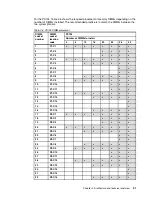
For the PS704, Table 2-6 shows the required placement of memory DIMMs depending on the
number of DIMMs installed. The recommended practice is to match the DIMMs between the
two system planars.
Table 2-6 PS704 DIMM placement
DIMM
socket
number
DIMM
socket
location
code
PS704
Number of DIMMs to install
4
8
12
16
20
24
28
32
1
P1-C1
x
x
x
x
x
x
x
x
2
P1-C2
x
x
x
x
3
P1-C3
x
x
x
x
4
P1-C4
x
x
x
x
x
x
x
x
5
P1-C5
x
x
x
x
x
x
6
P1-C6
x
x
7
P1-C7
x
x
8
P1-C8
x
x
x
x
x
x
9
P1-C9
x
x
x
x
x
x
x
10
P1-C10
x
x
x
11
P1-C11
x
x
x
12
P1-C12
x
x
x
x
x
x
x
13
P1-C13
x
x
x
x
x
14
P1-C14
x
15
P1-C15
x
16
P1-C16
x
x
x
x
x
17
P2-C1
x
x
x
x
x
x
x
x
18
P2-C2
x
x
x
x
19
P2-C3
x
x
x
x
20
P2-C4
x
x
x
x
x
x
x
x
21
P2-C5
x
x
x
x
x
x
22
P2-C6
x
x
23
P2-C7
x
x
24
P2-C8
x
x
x
x
x
x
25
P2-C9
x
x
x
x
x
x
x
26
P2-C10
x
x
x
27
P2-C11
x
x
x
28
P2-C12
x
x
x
x
x
x
x
29
P2-C13
x
x
x
x
x
30
P2-C14
x
31
P2-C15
x
32
P2-C16
x
x
x
x
x
Summary of Contents for BladeCenter PS703
Page 2: ......
Page 8: ...vi IBM BladeCenter PS703 and PS704 Technical Overview and Introduction...
Page 14: ...xii IBM BladeCenter PS703 and PS704 Technical Overview and Introduction...
Page 50: ...36 IBM BladeCenter PS703 and PS704 Technical Overview and Introduction...
Page 164: ...150 IBM BladeCenter PS703 and PS704 Technical Overview and Introduction...
Page 197: ......


