Table
1.
Blade
server
features
and
specifications
Microprocessor:
Two
IBM
Cell/B.E.
PowerPC
64-bit
architecture
processors
w/VMX
with
8
Synergistic
Processor
Units
(SPU),
512
KB
L2
cache,
256
KB
on
each
Synergistic
Processing
Engine
(SPE)
Memory:
Fixed
system
memory
configuration
of
2
GB
XDR
memory,
1
GB
per
Cell
Broadband
Engine
™
(Cell/B.E.)
processor.
Extra
memory
cannot
be
added
Integrated
functions:
v
Two
1
Gigabit
Ethernet
controllers
v
Local
service
processor
v
2
Cell/B.E.
companion
chips
each
providing
a
PCIe
and
a
single
PCI-X
interface
v
RS-485
interface
for
communication
with
BladeCenter
Management
Module
v
USB
Controller
Supported
Options:
v
Serial
attached
SCSI
(SAS)
expansion
card
v
High-Speed
InfiniBand
Card,
IB-4x
v
I/O
Buffer
DIMM
VLP
DDR2
512
MB,
total
1
GB
per
channel
Environment:
v
Ambient
temperature:
–
Operating
temperature:
25°C
to
35°C
(77°F
to
95°F).
Altitude:
0
to
2133
m
(0
to
7000
ft)
v
Humidity:
–
Operating
temperature:
8%
to
80%
Size:
v
Height:
24.5
cm
(9.7
inches)
v
Depth:
44.6
cm
(17.6
inches)
v
Width:
2.9
cm
(1.14
inches)
v
Maximum
weight:
5
kg
(13.2
lb)
Electrical
input:
v
Power
supply:
12
V
dc
Support
for
local
storage
The
BladeCenter
provides
a
SAS
solution
for
local
storage.
This
comprises
a
SAS
expansion
card
attached
to
the
blade
server,
a
SAS
switch
in
the
rear
of
the
chassis,
and
various
options
to
attach
storage
to
that
integrated
SAS
switch.
An
optional
SAS
expansion
card
is
available
for
the
BladeCenter
QS21.
Storage
can
be
attached
via
the
external
SAS
host
controller.
The
BladeCenter
QS21
supports
the
SAS
drives
of
the
IBM
System
Storage
™
DS3200
and
the
IBM
System
Storage
EXP3000
expansion
unit.
Check
the
IBM
BladeCenter
support
Web
site
for
details
of
supported
SAS
drives
at
http://www.ibm.com/support/us/en/.
Turning
on
the
blade
server
The
BladeCenter
QS21
is
hot-swappable
and
can
be
inserted
into
the
BladeCenter
unit
when
the
unit
is
already
powered
up.
However,
it
can
only
be
powered
on
by
one
of
the
methods
described
in
this
section.
While
the
blade
server
is
powering
up,
the
power-on
LED
on
the
front
of
the
server
is
lit.
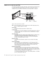
See
“Blade
server
controls
and
LEDs”
on
page
6
for
the
power-on
LED
states.
After
you
have
installed
the
BladeCenter
QS21
into
a
powered
up
BladeCenter
unit,
wait
until
the
power
on
LED
on
the
blade
server
flashes
slowly
before
turning
on
the
blade
server.
You
can
turn
on
the
blade
server
in
any
of
the
following
ways:
Using
the
power
control
button
You
can
press
the
power-control
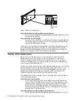
button
Figure
1
on
page
4
which
is
behind
the
control-panel
door
on
the
front
of
the
blade
server
if
local
power
control
is
enabled
for
the
blade
server.
Local
power
control
is
enabled
and
disabled
through
the
BladeCenter
Management
Module
Web
interface.
Chapter
1.
Introduction
3
Summary of Contents for BladeCenter QS21 Type 0792
Page 1: ...BladeCenter QS21 Type 0792 Problem Determination and Service Guide...
Page 2: ......
Page 3: ...BladeCenter QS21 Type 0792 Problem Determination and Service Guide...
Page 8: ...vi BladeCenter QS21 Type 0792 Problem Determination and Service Guide...
Page 46: ...28 BladeCenter QS21 Type 0792 Problem Determination and Service Guide...
Page 68: ...50 BladeCenter QS21 Type 0792 Problem Determination and Service Guide...
Page 142: ...124 BladeCenter QS21 Type 0792 Problem Determination and Service Guide...
Page 143: ......
Page 144: ...Part Number 42C4969 Printed in USA 1P P N 42C4969...

