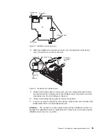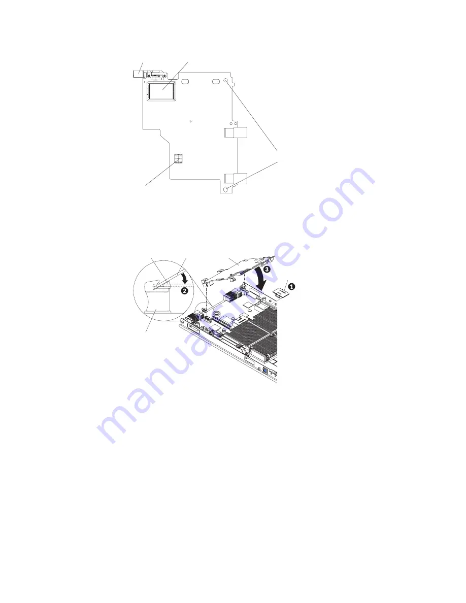
8.
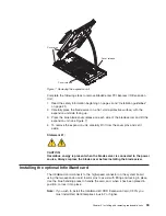
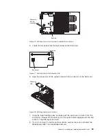
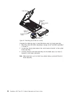
Slide
the
InfiniBand
card
locator
pin
holes
over
the
expansion
card
locator
pins.
The
card
rests
on
the
locator
pins.
9.
Check
that
the
ball
socket
on
the
card
is
over
the
corresponding
ball
stud
on
the
main
board
then
carefully
press
the
InfiniBand
card
into
position.
Use
the
blue
areas
only
to
avoid
damage
to
the
card.
10.
Check
that
the
blue
locking
clip
has
locked
into
position.
11.
If
you
do
not
want
to
install
any
other
options,
replace
the
cover
and
insert
the
BladeCenter
QS21
into
the
BladeCenter
unit.
Attention:
The
connectors
on
the
system
board
and
the
InfiniBand
card
are
not
designed
for
repeated
removal
or
replacement
of
components.
Avoid
removing
the
InfiniBand
card
once
it
is
in
position,
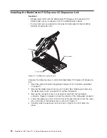
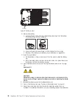
Connector
Locator pin holes
Ball socket
Locking clip
Figure
10.
InfiniBand
card
reverse
view
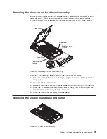
Expansion
connector
cover
Expansion card
Expansion
card
standoff
Locator pin
Figure
11.
Positioning
the
InfiniBand
card
Chapter
4.
Installing
and
removing
replaceable
units
35
Summary of Contents for BladeCenter QS21 Type 0792
Page 1: ...BladeCenter QS21 Type 0792 Problem Determination and Service Guide...
Page 2: ......
Page 3: ...BladeCenter QS21 Type 0792 Problem Determination and Service Guide...
Page 8: ...vi BladeCenter QS21 Type 0792 Problem Determination and Service Guide...
Page 46: ...28 BladeCenter QS21 Type 0792 Problem Determination and Service Guide...
Page 68: ...50 BladeCenter QS21 Type 0792 Problem Determination and Service Guide...
Page 142: ...124 BladeCenter QS21 Type 0792 Problem Determination and Service Guide...
Page 143: ......
Page 144: ...Part Number 42C4969 Printed in USA 1P P N 42C4969...

