


Adding
I/O
DDR2
memory
modules
This
section
describes
how
to
add
extra
I/O
DDR2
memory.
There
are
two
slots
per
Cell/B.E.
companion
chip
allowing
up
to
1
GB
of
memory
for
each
Cell/B.E.
companion
chip
for
I/O
buffering.
You
must
add
memory
as
pairs
of
dual
inline
memory
modules
(DIMMs).
You
may
fit
one
or
more
memory
modules
for
each
buffer,
but
each
I/O
buffer
must
use
the
same
type
of
memory
module
and
have
the
same
amount
of
memory.
The
minimum
amount
of
memory
you
can
add
is
512
MB
per
buffer,
or
one
module
per
buffer.
If
you
fit
a
single
pair
of
DIMMs
you
must
use
slots
JDIM00
and
JDIM11.
The
BladeCenter
QS21
supports
VLP
DDR2
512
MB
DIMMs
only.
Note:
The
DIMMs
are
used
as
memory
for
the
I/O
buffers
only.
You
cannot
increase
the
size
of
system
memory
which
is
fixed
at
1GB
for
each
Cell/B.E.
processor.
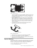
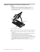
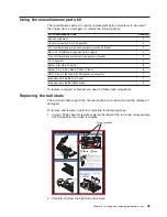
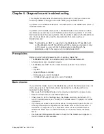
To
install
extra
I/O
buffer
memory,
complete
the
following
steps:
1.
Shut
down
the
BladeCenter
QS21.
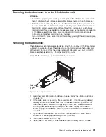
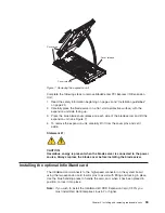
2.
Remove
the
BladeCenter
QS21
from
the
BladeCenter
unit.
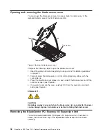
3.
Open
the
top
cover.
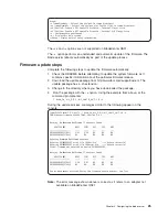
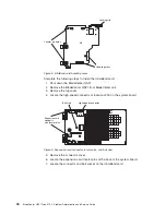
4.
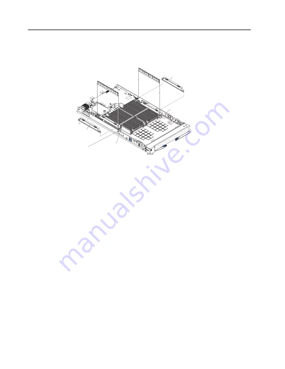
Locate
the
DIMM
slots
in
which
you
want
to
insert
the
I/O
DDR2
memory.
modules.
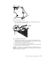
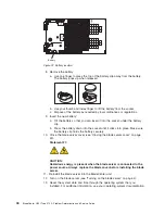
DIMM slot at JDIM00
DIMM slot at JDIM01
DIMM slot at JDIM11
DIMM slot at JDIM10
DIMM filler
DIMM
filler
Figure
12.
DIMM
slot
location
36
BladeCenter
QS21
Type
0792:
Problem
Determination
and
Service
Guide
Summary of Contents for BladeCenter QS21 Type 0792
Page 1: ...BladeCenter QS21 Type 0792 Problem Determination and Service Guide...
Page 2: ......
Page 3: ...BladeCenter QS21 Type 0792 Problem Determination and Service Guide...
Page 8: ...vi BladeCenter QS21 Type 0792 Problem Determination and Service Guide...
Page 46: ...28 BladeCenter QS21 Type 0792 Problem Determination and Service Guide...
Page 68: ...50 BladeCenter QS21 Type 0792 Problem Determination and Service Guide...
Page 142: ...124 BladeCenter QS21 Type 0792 Problem Determination and Service Guide...
Page 143: ......
Page 144: ...Part Number 42C4969 Printed in USA 1P P N 42C4969...


