


v
A
file
containing
the
change
history
for
the
QS22
Ethernet
Controller
firmware.
This
has
a
.chg
extension.
v
A
file
containing
the
update
package.
This
has
an
.sh
extension.
v
A
readme
file
for
the
update
package.
This
contains
specific
installation
and
configuration
information.
v
An
XML
file.
This
file
is
for
use
by
IBM
Systems
Management
tools,
including
IBM
Director
Update
Manager,
UpdateXpress
CD,
and
UpdateXpress
System
Pack
Installer.
Using
the
update
package
The
package
consists
of
an
file
with
a
.sh
extension
that
runs
from
the
Linux
prompt.
It
has
a
number
of
options.
To
see
what
options
are
available,
run
the
package
without
any
options
or
with
the
-h
switch:
#
./brcm_fw_nic_2.0.3-e-1_rhel5_cell.sh
In
the
example
shown
above,
brcm_fw_nic_2.0.3-e-1_rhel5_cell.sh
is
the
name
of
the
firmware
update
package.
The
file
name
changes
according
to
the
version
of
the
firmware.
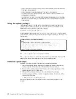
A
screen
similar
to
the
following
appears:
Usage:
-x
/someDirectory
-
Extract
the
payload
to
<some
directory>
-xr
/someDirectory
-
Extract
the
payload
plus
PkgSdk
files
to
<some
directory>
-xd
/dev/fd0
-
Create
a
DOS
bootable
diskette
-
Internel
floppy
drive
-xd
/dev/sda
-
Create
a
DOS
bootable
diskette
-
External
USB
floppy
drive
-u
-
Perform
update
unattended
-h
-
Display
this
help
screen
++debug
-
Display
helpful
debug
information
The
-xd
and
-x
options
are
not
supported
on
QS22.
The
-u
option
performs
an
unattended
and
automatic
update
of
the
firmware.
The
blade
server
reboots
automatically
as
part
of
the
update
process.
Firmware
update
steps
Complete
the
following
steps
to
update
the
firmware
automatically:
1.
Check
the
README
before
attempting
to
update
the
system
firmware
as
it
contains
specific
information
about
the
particular
firmware
release.
2.
Download
the
update
package
from
http://www.ibm.com/support/us/en/.
The
update
package
has
a
.sh
extension.
3.
Change
to
the
directory
where
you
have
downloaded
the
package.
4.
Run
the
package
with
the
-u
option.
Using
the
example
from
above,
at
the
command
prompt
enter:
./
brcm_fw_nic_2.0.3-e-1_rhel5_cell.sh
-u
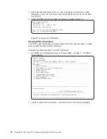
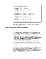
During
the
update
process,
messages
similar
to
the
following
appear
on
the
console:
24
BladeCenter
QS22
Type
0793:
Problem
Determination
and
Service
Guide
Summary of Contents for BladeCenter QS22 Type 0793
Page 1: ...BladeCenter QS22 Type 0793 Problem Determination and Service Guide...
Page 2: ......
Page 3: ...BladeCenter QS22 Type 0793 Problem Determination and Service Guide...
Page 8: ...Index 135 vi BladeCenter QS22 Type 0793 Problem Determination and Service Guide...
Page 44: ...26 BladeCenter QS22 Type 0793 Problem Determination and Service Guide...
Page 72: ...54 BladeCenter QS22 Type 0793 Problem Determination and Service Guide...
Page 156: ...138 BladeCenter QS22 Type 0793 Problem Determination and Service Guide...
Page 157: ......
Page 158: ...Part Number 44R5162 1P P N 44R5162...