

About this task
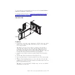
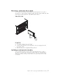
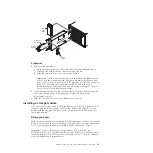
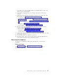
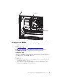
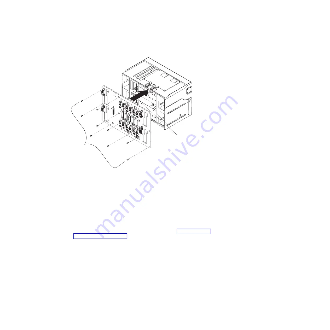
Guide pins
Screws (9)
Procedure
1.
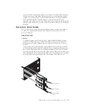
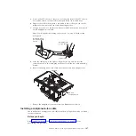
Make sure the release handles are closed and position the SPC chassis (shuttle)
so that the location where the midplane will be placed is facing up.
2.
Carefully place the midplane onto the SPC chassis, aligning the screw holes on
the midplane with the holes in the SPC chassis.
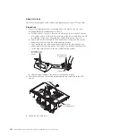
3.
Install the nine screws that attach the midplane to the SPC chassis.
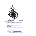
4.
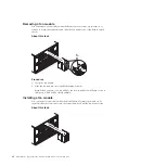
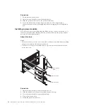
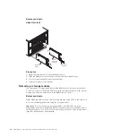
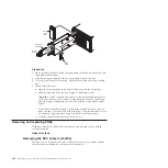
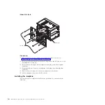
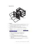
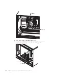
Reconnect the two upper fan-to-midplane cable plugs to the midplane
connectors.
5.
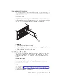
Reconnect the two lower fan-to-midplane cable plugs to the midplane
connectors.
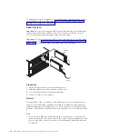
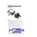
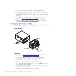
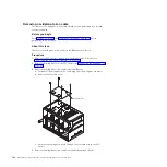
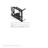
6.
Install the SPC chassis into the BladeCenter S chassis (see “Installing the SPC
chassis (shuttle)” on page 102).
7.
Update the vital product data (VPD) for the BladeCenter unit:
a.
Log into the advanced management module Web interface.
b.
In the navigation pane, click
Monitor
→
Hardware VPD
.
c.
Click
Chassis
.
d.
Click
Edit BladeCenter System Vital Product Data
.
e.
Obtain the model number and serial number on the ID label on the
BladeCenter; then, enter the information in the
Type/Model and Serial
Number fields
.
f.
If the advanced management module is using firmware version BPET54R or
older, restart the advanced management module.
Chapter 4. Removing and replacing BladeCenter components
105
Summary of Contents for BladeCenter S
Page 1: ...IBM BladeCenter S Type 7779 8886 Problem Determination and Service Guide ...
Page 2: ......
Page 3: ...IBM BladeCenter S Type 7779 8886 Problem Determination and Service Guide ...
Page 128: ...114 BladeCenter S Type 7779 8886 Problem Determination and Service Guide ...
Page 132: ...118 BladeCenter S Type 7779 8886 Problem Determination and Service Guide ...
Page 144: ...130 BladeCenter S Type 7779 8886 Problem Determination and Service Guide ...
Page 145: ......
Page 146: ... Part Number 94Y7083 Printed in USA 1P P N 94Y7083 ...


