Attention:
To maintain proper system cooling, each module bay must contain
either a module or a filler module; each blade bay must contain either a blade
server or a filler blade.
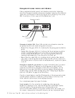
Front view
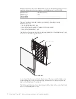
This section identifies the components, controls, and LEDs on the front of your
BladeCenter T unit.
Management-module bay 1
Power module 3
Power module 1
Power module 4
Power module 2
Front panel
Media tray
ESD connector
Management-module bay 2
CMM
1
CMM
2
Blade server 1
Blade server 8
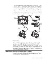
System service cards
These cards contain system service instructions and a writable area for your use.
The cards are located in a slot just above the management-module bays. To access
the service cards, slide out the cards as shown in the following illustration.
CM
M
1
CM
M
2
ESD
System service card
Chapter 1. General information
7
Summary of Contents for BladeCenter T
Page 1: ...BladeCenter T Type 8267 Hardware Maintenance Manual and Troubleshooting Guide ...
Page 2: ......
Page 3: ...BladeCenter T Type 8267 Hardware Maintenance Manual and Troubleshooting Guide ...
Page 16: ...xiv BladeCenter T Type 8267 Hardware Maintenance Manual and Troubleshooting Guide ...
Page 20: ...xviii BladeCenter T Type 8267 Hardware Maintenance Manual and Troubleshooting Guide ...
Page 52: ...32 BladeCenter T Type 8267 Hardware Maintenance Manual and Troubleshooting Guide ...
Page 102: ...82 BladeCenter T Type 8267 Hardware Maintenance Manual and Troubleshooting Guide ...
Page 126: ...106 BladeCenter T Type 8267 Hardware Maintenance Manual and Troubleshooting Guide ...
Page 138: ...118 BladeCenter T Type 8267 Hardware Maintenance Manual and Troubleshooting Guide ...
Page 139: ......
Page 140: ... Part Number 94Y7061 Printed in USA 1P P N 94Y7061 ...

