TOP
D
TOP
D
BTM
E
BTM
E
2
4
1
3
2
1
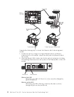
CRT
MJR
MNR
Connect directly to PC
Connect through an Ethernet switch
LAN module
192.168.70.125
192.168.70.135
192.168.70.155
Ethernet switch
RJ-45
connector
Standard Ethernet
cable
Standard
Ethernet
cables
Complete the following steps to connect the Ethernet cable to the management
module.
1.
Connect one end of a Category 5 or higher Ethernet cable to an Ethernet
connector on the LAN module. Connect the other end of an Ethernet cable to
the network.
2.
Check the Ethernet LEDs to make sure that the network connection is working.
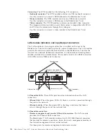
The following illustration shows the locations of the Ethernet LEDs on the LAN
module.
2
1
Ethernet link
Ethernet activity
Ethernet link LED
When this green LED is lit, there is an active connection through the
port to the network.
Ethernet activity LED
When this green LED is flashing, it indicates that there is activity
through the port over the network link.
22
BladeCenter T Type 8267: Hardware Maintenance Manual and Troubleshooting Guide
Summary of Contents for BladeCenter T
Page 1: ...BladeCenter T Type 8267 Hardware Maintenance Manual and Troubleshooting Guide ...
Page 2: ......
Page 3: ...BladeCenter T Type 8267 Hardware Maintenance Manual and Troubleshooting Guide ...
Page 16: ...xiv BladeCenter T Type 8267 Hardware Maintenance Manual and Troubleshooting Guide ...
Page 20: ...xviii BladeCenter T Type 8267 Hardware Maintenance Manual and Troubleshooting Guide ...
Page 52: ...32 BladeCenter T Type 8267 Hardware Maintenance Manual and Troubleshooting Guide ...
Page 102: ...82 BladeCenter T Type 8267 Hardware Maintenance Manual and Troubleshooting Guide ...
Page 126: ...106 BladeCenter T Type 8267 Hardware Maintenance Manual and Troubleshooting Guide ...
Page 138: ...118 BladeCenter T Type 8267 Hardware Maintenance Manual and Troubleshooting Guide ...
Page 139: ......
Page 140: ... Part Number 94Y7061 Printed in USA 1P P N 94Y7061 ...

