2.
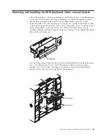
Position the LAN module into the rails inside the LAN module bay (see the
illustration of the KVM and LAN modules in “Removing and installing the
KVM (keyboard, video, mouse) module” on page 53).
3.
Push the LAN module into the bay until it stops. Make sure that it is snug.
4.
Turn each thumbscrew clockwise until it is finger tight. Make sure that you do
not overtighten the thumbscrews.
Removing and installing I/O modules
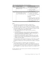
For blade server communication with the network, the BladeCenter T unit
supports up to four hot-swap I/O modules. Table 3 on page 57 identifies the types
of I/O modules that you can install in each I/O-module bay. Go to the IBM
Support website at http://www.ibm.com/supportportal/ to see the list of
supported I/O modules.
The BladeCenter T unit supports a minimum of one hot-swap Ethernet switch
module or pass-thru module, in I/O-module bay 1 or 2. This I/O module provides
an internal connection to an integrated Ethernet controller in all the blade servers
in the BladeCenter T unit, up to eight internal connections per I/O module. To
provide an internal connection for the second integrated Ethernet controller in each
blade server, install an Ethernet switch module or pass-thru module in the
available I/O-module bay of the pair (I/O-module bay 1 or bay 2). The
management modules are connected to the switch module through the backplane
using a transformerless 100 Mbps connection and an I2C interface.
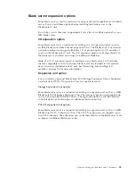
The BladeCenter T unit supports two additional I/O modules in I/O-module bays
3 and 4. Each of these I/O modules provides an internal connection to one of the
two network-interface controllers on each of the I/O expansion options that are
installed on blade servers in the BladeCenter T unit. The I/O module must be
compatible with the network interface on each of the I/O expansion options. For
example, if you install a Fibre Channel I/O expansion card on a blade server, the
I/O modules that you install in I/O-module bays 3 and 4 must be Fibre Channel
switch modules or pass-thru modules.
Important:
The switch modules in I/O module bays 3 and 4 and all blade server
interface options in the BladeCenter T unit, must use the same interface type. For
example, if you install an Ethernet interface option on a blade server, the switch
modules that you install in I/O module bays 3 and 4 must be Ethernet. All other
interface options in the BladeCenter T unit must also be Ethernet interface options.
Note:
You can use a pass-thru module in any I/O-module bay, provided that the
associated controller in the blade servers or I/O expansion options is compatible
with it.
The following table summarizes the types of modules that can be used in each
I/O-module bay. See “Rear view” on page 12 for the location of the I/O-module
bays on the BladeCenter T unit.
56
BladeCenter T Type 8267: Hardware Maintenance Manual and Troubleshooting Guide
Summary of Contents for BladeCenter T
Page 1: ...BladeCenter T Type 8267 Hardware Maintenance Manual and Troubleshooting Guide ...
Page 2: ......
Page 3: ...BladeCenter T Type 8267 Hardware Maintenance Manual and Troubleshooting Guide ...
Page 16: ...xiv BladeCenter T Type 8267 Hardware Maintenance Manual and Troubleshooting Guide ...
Page 20: ...xviii BladeCenter T Type 8267 Hardware Maintenance Manual and Troubleshooting Guide ...
Page 52: ...32 BladeCenter T Type 8267 Hardware Maintenance Manual and Troubleshooting Guide ...
Page 102: ...82 BladeCenter T Type 8267 Hardware Maintenance Manual and Troubleshooting Guide ...
Page 126: ...106 BladeCenter T Type 8267 Hardware Maintenance Manual and Troubleshooting Guide ...
Page 138: ...118 BladeCenter T Type 8267 Hardware Maintenance Manual and Troubleshooting Guide ...
Page 139: ......
Page 140: ... Part Number 94Y7061 Printed in USA 1P P N 94Y7061 ...

