background image

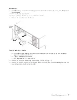
a.

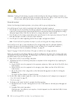
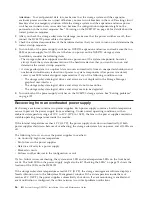
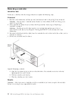
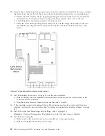
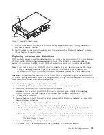
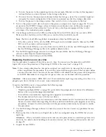
Open the two release levers as shown in the illustration. The controller moves out of the bay
approximately 0.6 cm (0.25 inch).

b.

Pull the controller out of the bay.

c.

Place the controller on a level surface.

Attention:

The DCS3700 replacement controller ships with a temporary filler. Place the temporary

filler in the controller chassis bay after the failed controller is removed, to maintain proper airflow
and cooling.

9.

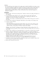
Remove the cover (see “Removing and installing a cover” on page 91).

10.

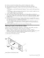
If an optional SAS or Fibre Channel host daughter card is installed in the controller, remove the host

daughter card and set it aside (see "Removing the optional host interface adapter").

11.

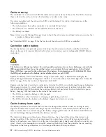
Remove the battery from the failed controller.

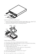
a.

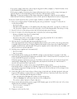
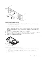
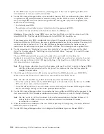
Loosen the blue captive fastener until the battery can move in the direction that is indicated by
the arrow.

b.

Slide the battery unit out of the controller in the direction that is indicated by the arrow.

c.

Set the battery aside.

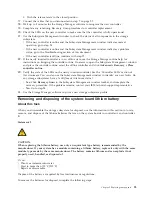
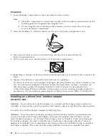
Figure 61. Removing and replacing a controller

Battery connector

Captive fastener

Memory cache battery

Figure 62. Removing the battery unit from the controller

Chapter 5. Replacing components

93

Summary of Contents for DCS3700

Page 1: ...IBM System Storage DCS3700 Installation User and Maintenance Guide...

Page 2: ......

Page 3: ...IBM System Storage DCS3700 Installation User and Maintenance Guide...

Page 4: ...the general information in the Safety on page xi and Notices on page 159 sections First Edition May 2011 Printed in the U S A Copyright IBM Corporation 2011 US Government Users Restricted Rights Use d...

Page 5: ...midity 18 Altitude 19 Airflow and heat dissipation 19 Shock and vibration requirements 19 Acoustic noise 20 Electrical requirements 20 Power and site wiring requirements for models with power supply a...

Page 6: ...101 Replacing hot swap hard disk drives 103 Replacing multiple DDMs 104 Replacing all DDMs at the same time 105 Replacing the drives one at a time 107 Replacing an ac power supply 109 Replacing a batt...

Page 7: ...nt 164 People s Republic of China Class A Electronic Emission Statement 165 Russia Electromagnetic Interference EMI Class A Statement 165 Taiwan Class A Electronic Emission Statement 165 Taiwan Contac...

Page 8: ...vi IBM System Storage DCS3700 Installation User and Maintenance Guide...

Page 9: ...multiple hosts 59 40 Example of DCS3700 connected to a single BladeCenter unit 60 41 Dual controller direct attached Fibre Channel connection to two HBAs in the same host redundant host connection 62...

Page 10: ...t tumbler located above the drawer guide 126 88 DCS3700 storage subsystem enclosure parts list 137 89 Front rack mounting template 144 90 Rear rack mounting template 145 91 Top View of non IBM Rack Sp...

Page 11: ...00 sound levels 20 12 DCS3700 ac power requirements 20 13 Fibre Channel port LEDs 75 14 Fan assembly LEDs 77 15 Drive drawer LEDs 78 16 Disk drive LEDs 79 17 Drive state indicated by the LEDs 79 18 Co...

Page 12: ...x IBM System Storage DCS3700 Installation User and Maintenance Guide...

Page 13: ...NGER Electrical current from power telephone and communication cables is hazardous To avoid a shock hazard v Do not connect or disconnect any cables or perform installation maintenance or reconfigurat...

Page 14: ...ed note the following v Do not remove the covers Removing the covers of the laser product could result in exposure to hazardous laser radiation There are no serviceable parts inside the device v Use o...

Page 15: ...er cord To remove all electrical current from the device ensure that all power cords are disconnected from the power source 1 2 Statement 8 CAUTION Never remove the cover on a power supply or any part...

Page 16: ...me premises as this equipment v Switching or disconnecting devices shall not be in the earthed circuit conductor between the dc source and the point of connection of the earthing electrode conductor S...

Page 17: ...on this product or cords associated with accessories sold with this product will expose you to lead a chemical known to the State of California to cause cancer and birth defects or other reproductive...

Page 18: ...xvi IBM System Storage DCS3700 Installation User and Maintenance Guide...

Page 19: ...units FRUs such as hard disk drives power supplies fan assemblies environmental service modules ESMs drive drawers and SFP modules Chapter 6 Hardware maintenance on page 129 describes problems and sym...

Page 20: ...ing information or the diagnostic programs might tell you that you need additional or updated device drivers or other software Finding Storage Manager software controller firmware and README files DS...

Page 21: ...rvices sl products For more information about the IBM Support Line and other IBM services go to the following Web sites v www ibm com services v www ibm com planetwide Hardware service and support You...

Page 22: ...xx IBM System Storage DCS3700 Installation User and Maintenance Guide...

Page 23: ...on page 3 The DCS3700 is a 4U rack mountable storage enclosure that supports up to two redundant dual active RAID storage controllers or environmental service modules depending on the model The DCS37...

Page 24: ...rage and networking Using a Fibre Channel arbitrated loop FC AL more than 100 fibre channel devices can be supported compared to 15 small computer system interface SCSI devices Operating system suppor...

Page 25: ...terface adapter Support for 6 Gbps SAS 8 Gbps FC Redundant controllers or ESMs power supply and fan assemblies Hot swap technology for controllers and power supply v User interface Built in power acti...

Page 26: ...contain additional materials that are not shown in the following illustration Support rails Storage enclosure M5 x 8 mm screws 16 PDU jumper cord Rear brackets Bezel Clip nuts 4 Fan assembly 2 Power s...

Page 27: ...support notifications For more information about how to register for support notifications see the Stay Informed section of the IBM Disk Support Web site Best practices guidelines To ensure optimal o...

Page 28: ...e controller will be able to optimally access all of your storage subsystems v The storage subsystem supports simultaneous power up to the system components however you should always follow the power...

Page 29: ...ntain the availability of your system while a hot swap device is removed installed or replaced The DCS3700 expansion unit is the storage expansion enclosure specifically designed for use with the DCS3...

Page 30: ...ve drive drawers Disk Drive Modules DDMs The DSC3700 supports up to 60 DDMs in five drive drawers that are accessible from the front of the storage expansion enclosure The disk drawer planar board sup...

Page 31: ...y slot A SBB A and controller B is installed in storage bridge bay slot B SBB B All connections to the hosts and the expansion enclosures are made through the controllers Figure 4 shows the location o...

Page 32: ...hat is used to connect expansion enclosures to the storage system The two SAS expansion ports one on each controller are used to form a redundant drive channel Ethernet management ports The Ethernet c...

Page 33: ...failure Figure 6 shows the locations of the cache battery and memory cache DIMM in the controller The battery chargers in the power supplies perform a battery learn test when the storage subsystem is...

Page 34: ...e ID are referred to as x10 and x1 digits The enclosure ID provides a unique identifier for each enclosure in the storage subsystem The storage management software automatically sets the enclosure ID...

Page 35: ...ugh the enclosure from front to back across the drives The fans provide redundant cooling which means that if one of the fans fails the remaining fan assembly continues to provide sufficient cooling t...

Page 36: ...site orientations If the fan assembly cannot be fully inserted in the fan assembly bay rotate it 180 degrees and reinsert it In addition there are notches on the top and bottom of the fan assembly bay...

Page 37: ...M firmware and the drive firmware must be installed to ensure optimal functionality manageability and reliability Unless stated otherwise you can find the latest publications firmware and host softwar...

Page 38: ...ions Each method uses the DS Storage Manager client that manages the DCS3700 storage subsystem with the attached storage expansion enclosure Method One Go to the Subsystem Management window and select...

Page 39: ...age expansion enclosure installation service and operation Area requirements The floor space at the installation site must provide enough strength to support the weight of the storage subsystem and as...

Page 40: ...issipation shock and vibration requirements and acoustic noise levels Temperature and humidity Table 7 lists the acceptable temperature and humidity ranges for the DCS3700 storage expansion enclosure...

Page 41: ...ions These values assume the power supplies have a 88 percent efficiency and a power factor of 0 99 These tabulated power and heat dissipation values are typical for the storage subsystem Maximum conf...

Page 42: ...nd wiring storage subsystem ac power requirements and power cord routing instructions Consider the following information when preparing the installation site v Protective ground Site wiring must inclu...

Page 43: ...ling See Airflow and heat dissipation on page 19 for heat output airflow and cooling specifications Note In general disk subsystem reliability tends to decrease as the ambient temperature of the envir...

Page 44: ...sle Perforated tiles or gratings back back T42 racks T42 racks T42 racks Cold aisle Hot aisle Air conditioner back front front front Airflow Figure 14 Example of cold aisle hot aisle rack configuratio...

Page 45: ...installed the unit weighs 102 1 kg 225 lb It takes two specially trained IBM personnel with a lifting device to safely lift this unit 2 A fully populated DCS3700 weighs approximately 102 1 kg 225 lb...

Page 46: ...also result in a time and date to return the tool that is different from what you need v Phone number and customer contact v Account code 98577 v Time and date of delivery v Accurate destination addr...

Page 47: ...stem Storage DS Storage Manager Version 10 Installation and Host Support Guide for your operating system for instructions on how to install the DS Storage Manager host software 9 Turn on the DCS3700 i...

Page 48: ...that contains DCS3700 storage enclosures see Relocating the DCS3700 on page 65 for additional information Note For more information about how to use a lift tool see the documentation that came with th...

Page 49: ...e boxes are empty v Box containing the mounting hardware kit v Box containing storage enclosure handles v Box containing the power cords and documentation 2 Check the items in the preceding list to ma...

Page 50: ...t are not shown in the following illustration Support rails Storage enclosure M5 x 8 mm screws 16 PDU jumper cord Rear brackets Bezel Clip nuts 4 Fan assembly 2 Power supply 2 Controller or ESM 2 Driv...

Page 51: ...de screwdriver v A No 2 Phillips screwdriver or an M5 hex driver v Anti static protection Tools and hardware required Gather the tools and equipment you will need for installation These might include...

Page 52: ...ecifications for non IBM rack installation on page 147 v Do not extend more than one device out of the rack cabinet at the same time v To ensure proper airflow do not block the air vents 15 cm 6 in of...

Page 53: ...n the following templates are round The holes in your rack might be round square or threaded 3U 3U 2U 2U 1U 1U 0U 0U Rail assembly front left Rail assembly front right FRONT Rack Mounting Template 4U...

Page 54: ...e you place the support rails in the rack depends on where you intend to position the storage enclosure Use the front and rear rack mounting templates in Figure 15 on page 31 and Figure 16 to align th...

Page 55: ...rt rail loosen the two rail adjustment screws with a medium flat blade screwdriver The adjustment screws are used to lock the support rails at a certain length Note The support rails are not marked as...

Page 56: ...e racks Failure to do so will cause the storage enclosure to fit unevenly in the rack 11 Locate the two rear brackets four M5 screws four washers and four clip nuts that are supplied with the storage...

Page 57: ...the DCS3700 into a rack To install the storage enclosure complete the following steps Note For more information about how to use a lift tool see the documentation that came with the lift tool 1 Prepa...

Page 58: ...ined service technicians or a lift tool and professional movers slide the storage enclosure off of the side of the shipping box and onto the lift tool Align it in front of the rack 3 Put the rear edge...

Page 59: ...n can damage them Always wait at least 90 seconds from when you turn off the power until you turn it on again 2 The installation order within each drawer is from left to right in rows Slots 1 4 7 and...

Page 60: ...drawer as shown in the illustration Starting with the top drive drawer in the storage enclosure pull the levers on each side of the drawer out and cam away from the chassis to release the drawer Driv...

Page 61: ...e drive drawer into the storage enclosure until it clicks and close the levers on each side of the drawer Attention Make sure you push both levers back against the drive drawer completely so that the...

Page 62: ...40 IBM System Storage DCS3700 Installation User and Maintenance Guide...

Page 63: ...in its permanent location you must cable it to hosts expansion units and other external devices depending on your hardware configuration Controller connectors with SAS host port adapters Figure 18 sho...

Page 64: ...he storage subsystem configuration In a dual controller or ESM configuration both enclosure IDs are identical under normal operating conditions Each DCS3700 storage system and DCS3700 expansion enclos...

Page 65: ...der the following precautions v When you route the cable along a folding cable management arm leave enough slack in the cable v Route the cable away from places where it can be damaged by other device...

Page 66: ...ng wave and short wave SFPs Attention In addition do not use long wave SFPs in any of the FC ports in the FC drive loops Long wave SFPs are not supported for use in the drive ports of storage expansio...

Page 67: ...ot view directly with optical instruments and avoid direct exposure to the beam Attention When you handle static sensitive devices take precautions to avoid damage from static electricity For details...

Page 68: ...For more information see Handling fibre optic cables on page 47 2 Unlock the SFP module latch v For SFP modules that contain plastic tabs unlock the SFP module latch by pulling the plastic tab outwar...

Page 69: ...than 38 mm 1 5 in v When storing excess or unused fibre optic cables do not bend the cables to a diameter of less than 76 mm 3 in or a radius less than 38 mm 1 5 in or wrap them around themselves See...

Page 70: ...ch port or fibre channel host bus adapter port See Figure 28 for an illustration of the LC LC Fibre Channel cable For more information about cabling these devices see the documentation that comes with...

Page 71: ...owing Laser radiation when open Do not stare into the beam do not view directly with optical instruments and avoid direct exposure to the beam 1 Read the information in Handling fibre optic cables on...

Page 72: ...to release the latches before you remove the cable from the SFP module v Ensure that the levers are in the released position when you remove the cable v Do not grasp the SFP module plastic tab when y...

Page 73: ...controller or the SAS Out connector of another DCS3700 expansion enclosure SAS Out connector Connect a SAS cable to this connector and to the SAS In connector of another DCS3700 Note Each ESM contains...

Page 74: ...nect the of the DCS3700 expansion enclosure to the next DCS3700 expansion enclosure in the chain a Connect one end of a SAS cable to the Out SAS connector on the ESM located in SBB slot A of the DCS37...

Page 75: ...Figure 34 Single Expansion Enclosures Chapter 3 Cabling the DCS3700 53...

Page 76: ...Figure 35 Dual Expansion Enclosures 54 IBM System Storage DCS3700 Installation User and Maintenance Guide...

Page 77: ...rage subsystem management methods Before you configure the storage subsystem determine which method of storage subsystem management you want to use You can manage the storage subsystems in either of t...

Page 78: ...each management station one pair per storage subsystem You will connect the cables to each storage system controller later when you install the storage subsystem Figure 37 on page 57 shows the direct...

Page 79: ...3700 on page 60 to connect the other end of each cable to the controller Connecting SAS hosts to the DCS3700 The DCS3700 can support up to 28 hosts when attached to the SAS Connectivity Module for IBM...

Page 80: ...ed in each controller a maximum of four redundant host connection are supported See Direct attached dual controller connections for illustrations of host connections Direct attached dual controller co...

Page 81: ...are supported by the DCS3700 storage system v Make sure that an Advanced Management Module is installed in the BladeCenter chassis The latest level of management module firmware is available at http w...

Page 82: ...orage system to any SAS port on an IBM BladeCenter SAS Connectivity Module that is installed in a BladeCenter unit port 3 is recommended 2 To create a redundant host connection connect a SAS cable fro...

Page 83: ...t the Fibre Channel cables to the SFP modules in the controller host ports and to either the SFP modules in the Fibre Channel switch or the optical interface connector on the host bus adapters 3 Repea...

Page 84: ...e 41 Dual controller direct attached Fibre Channel connection to two HBAs in the same host redundant host connection Figure 42 Dual controller direct attached Fibre Channel connections to multiple HBA...

Page 85: ...nel switches are connected together through the Inter Switch Link ISL to form a single SAN fabric In the following illustration the Fibre Channel switches are not connected together through an ISL Eac...

Page 86: ...ted together Each switch forms its own SAN fabric Figure 44 Example of a dual Fibre Channel SAN fabric configuration Figure 45 Example of two storage subsystems in a dual Fibre Channel SAN environment...

Page 87: ...supply tie the power supply cord to the strap to provide strain relief and to prevent the power cord from accidently being unplugged 2 Connect the power cable to the power supply 3 Continue with Powe...

Page 88: ...66 IBM System Storage DCS3700 Installation User and Maintenance Guide...

Page 89: ...Profile v SAS PHY error log In addition you should also collect event logs for the host servers that have mapped logical drives from the storage subsystem Attention Save these event log files to a ser...

Page 90: ...ectly seated v Make sure that all drives are correctly seated v Make sure that cables are managed correctly v Ensure proper air flow and temperature for all components in the storage configuration You...

Page 91: ...ring the startup process 4 Depending on the number of storage enclosures in the configuration the storage subsystem might take up to 10 minutes to fully power on While each storage enclosure powers on...

Page 92: ...llers Follow the instructions in the operating system documentation to make the new logical drives accessible to the operating system Do not proceed with the configuration setup until you have complet...

Page 93: ...res to repair the failure Amber needs attention LEDs do not necessarily indicate which component has failed or must be replaced or which type of recovery procedure you must perform In some cases such...

Page 94: ...r the expansion enclosures 2 Controller firmware 3 Controller NVSRAM 4 Drive firmware Troubleshooting the storage subsystem The Storage Manager software is the best way to monitor the storage subsyste...

Page 95: ...ng power on the LEDs flash intermittently as the storage subsystem and components complete the power on process In addition to checking for faults you can use the LEDs on the front of the storage subs...

Page 96: ...em with the SAS link that requires service action The normal condition of this LED is off SAS link up LED green When this LED is lit it indicates that the link is established between the controller an...

Page 97: ...d 4 Gbps These LEDs in combination indicate the speed of the Fibre Channel host port Table 13 Fibre Channel port LEDs 2 Gbps LED 4 Gbps LED Host port speed On Off 2 Gbps Off On 4 Gbps On On 8 Gbps Off...

Page 98: ...e SAS cable is successful OK to remove LED blue This LED is supported only when the EXP3500 is attached to a DS3500 controller Do not remove the ESM unless this blue LED is lit Fault LED amber When th...

Page 99: ...primary LEDs on the DCS3700 ac power supplies 1 Standby power LED green Future use only 2 DC power LED green When this green LED is lit it indicates that the DCS3700 is turned on and is supplying 5 vo...

Page 100: ...he drives in the drawer is lit 2 Service Action Required Fault Off On Amber A fault exists within the drive drawer 3 14 Drive Activity for drives 1 to 12 in the drawer Note The associated disk drive i...

Page 101: ...there is no drive I O activity On Off Off Normal operation Drive I O activity is occurring Blinking Off Off Service Action Required A fault condition exists and the drive is offline On On On Power is...

Page 102: ...re x is a hexadecimal digit indicate storage subsystem state information In general these codes are displayed only when the storage subsystem is in a non operational state The storage subsystem might...

Page 103: ...ot read midplane EEPROMs LP Missing Drive Port Mapping table Ln ESM not valid for enclosure H2 Invalid Incomplete Configuration LF Lockdown with limited SYMbol support LH Controller firmware mismatch...

Page 104: ...or when the battery fault LEDs light See Controller LEDs on page 74 for the location of the battery fault LED Replace only the battery unit that is indicated as failed by the LEDs or in the Storage Ma...

Page 105: ...e or software procedure require that you turn off the power v An IBM technical support representative instructs you to turn off the power v A power outage or emergency situation occurs see Restoring p...

Page 106: ...power after an unexpected shutdown on page 85 Figure 9 on page 13 shows the locations of the power switches on a storage subsystem Before you proceed use the Storage Manager software to determine the...

Page 107: ...helps to safeguard your equipment from potential damage due to electrical surges when power is restored If the storage subsystem loses power unexpectedly it might be due to a hardware failure in the...

Page 108: ...ical user interface The storage subsystem logical drives and arrays do not come online The storage subsystem logical drives and arrays seem to be degraded 5 Turn on both of the power supply switches o...

Page 109: ...air has cooled the power supplies should turn on automatically If the power supplies restart automatically the controllers will reset and return to normal operation 5 Did the power supplies restart au...

Page 110: ...bleshoot that component See Checking the LEDs on page 73 c When the procedure is completed select Recheck in the Recovery Guru This runs the Recovery Guru again to make sure that the problem is correc...

Page 111: ...If an amber LED is lit and the associated Service Action Allowed LED is not lit you must perform additional diagnostics before you can remove the indicated component Use the Recovery Guru instruction...

Page 112: ...s of communication with devices See Chapter 3 Cabling the DCS3700 in this document for more information 3 Disconnect all attached interface cables from the controller Be sure to label each cable so th...

Page 113: ...practices information found in the prolog and Chapter 1 of this document 2 Align the cover on the controller and slide it toward the front of the controller to install it Replacing a controller About...

Page 114: ...n before you can remove the controller Use the Recovery Guru in the Subsystem Management window to identify and correct any additional failures If there are none proceed with step 5 to replace the con...

Page 115: ...r on page 91 10 If an optional SAS or Fibre Channel host daughter card is installed in the controller remove the host daughter card and set it aside see Removing the optional host interface adapter 11...

Page 116: ...on page 93 into the new controller a Slide the battery into the controller until the battery connector pins are firmly seated in the controller battery connector b Turn the captive fastener clockwise...

Page 117: ...ontroller See the Controller LEDs section of this document You can also use the Subsystem Management window to identify any new faults Do any storage subsystems have a fault Needs Attention status v Y...

Page 118: ...yrecycle shtml or contact your local waste disposal facility In the United States IBM has established a return process for reuse recycling or proper disposal of used batteries For information on prope...

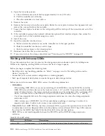
Page 119: ...wo release levers as shown in the illustration The controller moves out of the bay approximately 0 6 cm 0 25 inch b Pull the controller out of the bay c Place the controller on a level surface 5 Remov...

Page 120: ...tall the cover see Removing and installing a cover on page 91 13 Insert the controller into the chassis a Make sure that the release levers on the controller are in the open position b Slide the contr...

Page 121: ...controller See the Controlling LEDs section in this document You can also use the Subsystem Management window to identify any new faults Do any storage subsystems have a fault Needs Attention status...

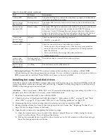
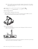
Page 122: ...ng static sensitive devices on page 25 v Ensure that your current system configuration is working properly v Back up all important data before you make changes to data storage devices Before you insta...

Page 123: ...can be safely removed v Hot swap hardware The DCS3700 contains hardware that enables you to replace a failed DDM without turning off the storage expansion enclosure You can continue to operate your sy...

Page 124: ...ise the drive handle to the vertical position as shown in Figure 69 b Align the two raised buttons on each side over the matching gap in the drive channel on the drawer as shown in Figure 70 c Lower t...

Page 125: ...drawer and position Complete the following steps to replace a hot swap DDM 1 Use the Storage Management client software to print a new storage system profile 2 Determine the location of the DDM that...

Page 126: ...ready for import and also might be incompatible or uncertified Use the Recovery Guru to diagnose the problem 11 Use the DS Storage Manager subsystem management window to verify that the DDM is shown...

Page 127: ...array any new DDM failure will cause the array to fail causing a loss of data availability and even a loss of data The duration of the reconstruction and copyback process can be quite long depending...

Page 128: ...o the host before you turn off power to the storage subsystem If the host must stay powered on to support an existing network see the operating system documentation for information about disconnecting...

Page 129: ...ocedure on RAID 0 logical drives use the procedure in Replacing all DDMs at the same time on page 105 Note If your storage subsystem has hot spares assigned you might want to unassign the hot spares w...

Page 130: ...uring data reconstruction the amber Drive fault LED might come on for a few minutes then turn off when the green Drive activity LED begins flashing A flashing Drive activity LED indicates that data re...

Page 131: ...r supply If any of these conditions occurs one or both power supplies will shut down If the power remains off does not automatically restart make sure that the environment is optimal no overheating ha...

Page 132: ...the storage enclosure until you v Review the replacement procedure in this section v Have the replacement power supply and are ready to install it in the enclosure L001 Procedure 1 If necessary use t...

Page 133: ...red outlets v When possible use one hand only to connect or disconnect signal cables v Never turn on any equipment when there is evidence of fire water or structural damage v Disconnect the attached p...

Page 134: ...the receptacle that the power supply is connected to The power cord might be faulty Go to step 17 v The fault and ac power LEDs are lit but the dc power LED is off The power supply is faulty Turn off...

Page 135: ...to minimize any performance impact due to the disabling of the write caching function Attention When you handle static sensitive devices take precautions to avoid damage from static electricity For d...

Page 136: ...nit out of the controller in the direction that is indicated by the arrow c Dispose of the battery as required by local ordinances or regulations For more information see the IBM Systems Environmental...

Page 137: ...d time period before you install or remove the DIMM Follow the instructions in this procedure exactly Attention To avoid overheating the storage enclosure and causing damage to its components replace...

Page 138: ...assis a Open the two release levers as shown in the illustration The controller moves out of the bay approximately 0 6 cm 0 25 inch b Pull the controller out of the bay c Place the controller on a lev...

Page 139: ...firmly seated in the connector If there is a gap between the DIMM and the retaining clips the DIMM has not been correctly inserted open the retaining clips remove the DIMM and then reinsert it 6 Inst...

Page 140: ...he flash memory device into the slot until the flash memory is fully seated Replacing the bezel Use this procedure to remove and replace the bezel on the front of the storage expansion enclosure You m...

Page 141: ...Manager software identifies failed parts Do not remove the failed part from the storage enclosure until you v Review the replacement procedure for the failed part in this guide v Locate screw drivers...

Page 142: ...to replace it with a new FRU Attention v To prevent damage from overheating replace a failed fan assembly FRU within 5 minutes of removal If replacing it will take longer than 5 minutes stop all I O a...

Page 143: ...ll the way into the bay Note Although both fan assemblies left and right are identical they are seated in the DCS3700 enclosure in opposite orientations If the fan assembly cannot be fully inserted in...

Page 144: ...ossible stop the I O activity to the storage expansion enclosure If it is not possible to stop the I O activity perform the drive drawer replacement during a period of low I O activity b Is power appl...

Page 145: ...isconnect The top cable chain is attached to drive drawer 1 The bottom cable chain is attached to drive drawer 5 CAUTION Verify that you have identified the correct drive drawer before removing the ca...

Page 146: ...th the power turned on you must reinstall the fan assembly within 10 minutes Otherwise the equipment could overheat g Disconnect the left cable chain mounting bracket from the midplane Insert your fin...

Page 147: ...ives before removing them in the next step c Remove all of the disk drive modules from the drive drawer See Replacing hot swap hard disk drives on page 103 for the steps to remove a DDM d Slide the dr...

Page 148: ...bracket to the drive drawer h Connect the right cable chain mounting bracket to the midplane Use a flashlight if necessary so that you can see the connector on the mounting bracket connect to the mid...

Page 149: ...hould be turned off automatically by the controllers If it is not turned off automatically open the script window for the DCS3700 storage subsystem and execute the following SMcli script command set e...

Page 150: ...128 IBM System Storage DCS3700 Installation User and Maintenance Guide...

Page 151: ...Determination Guide may provide you with additional diagnostic aids Solving problems This section contains information to help you solve some of the problems you might have with your DCS3700 storage s...

Page 152: ...ntroller battery fault LED Battery unit failure Use the Storage Manager software to confirm the failure then replace the failed battery unit storage controller SAS link service action LED SAS cable fa...

Page 153: ...e or verify the link speed If all the iSCSI port LEDs are off suspect failure of the iSCSI host daughter card One of the drive drawers is not fully closed Use Storage Manager software to identify the...

Page 154: ...DCS3700 v DCS3700 does not have the correct firmware version All green LEDs are off All components Subsystem power is off Make sure that all storage subsystem power cables are connected and that the p...

Page 155: ...orted storage subsystem Verify that the expansion enclosure is connected to a supported storage subsystem See http www ibm com systems storage disk One or more green LEDs are off continued All drives...

Page 156: ...supply Replace defective power cables Power supply failure Check the fault LED on the power supply If the LED is lit replace the failed component Faulty disconnect device Check and install a new 30A r...

Page 157: ...ng components on page 89 for more information Incorrect firmware version Make sure that the DCS3700 has the correct firmware version In a dual controller storage subsystem one controller has failed an...

Page 158: ...ager Subsystem Management window Turn off the SAA LED by using the appropriate script command in the script window v The script command to turn off a drive drawer SAA LED is set enclosure enclosureID...

Page 159: ...Power supply 1755w AC 90Y8593 4 Controller with 2GB Cache DIMM no host interface adapter no backup battery module no flash memory 90Y8596 4 Controller with 4GB Cache DIMM no host interface adapter no...

Page 160: ...1 9 Drive drawer assembly includes right and left cable chains 90Y8594 10 2TB 6Gbps NL SAS 7200 RPM disk drive module 90Y8597 11 Bezel 90Y8592 12 Handle 59Y5526 HDD carrier 69Y2773 Cable SAS 1M 39R653...

Page 161: ...representative Identification numbers Record and retain the following information Product name IBM System Storage DCS3700 Storage System Machine type 1818 Model number 80C Serial number Product name I...

Page 162: ...d the host or Domain Name System DNS table The information is also helpful if you add storage subsystems after initial installation Refer to your DS Storage Manager documentation for detailed instruct...

Page 163: ...tion record Storage subsystem name Management method Controllers Ethernet and IP addresses and host name Host IP address and host name Controller A Controller B Finance Direct Hardware Ethernet addres...

Page 164: ...responding drive drawer and position number Attention If you replace a hard disk drive in the wrong drive bay it might cause a loss of data Table 25 Hard disk drive record Bay Number Hard disk drive s...

Page 165: ...44 and Figure 90 on page 145 to identify the proper locations for inserting M5 screws when mounting the support rails and DCS3700 to a rack The locations for the M5 screws are highlighted in the templ...

Page 166: ...right FRONT Rack Mounting Template 4U 4U Install second Install first Install second Install first Install first Install first Install second Install second Figure 89 Front rack mounting template 144...

Page 167: ...Rail assembly rear left Rail assembly rear right Printed in the U S A REAR Rack Mounting Template Rail mounting guide 4U 4U Rear bracket Rear bracket Figure 90 Rear rack mounting template Appendix B R...

Page 168: ...146 IBM System Storage DCS3700 Installation User and Maintenance Guide...

Page 169: ...ETL ETLc mark c CSA The European Union requires a CE mark and a Manufacturer s Declaration of Conformity DOC Certified products should have the NRTL logos or marks somewhere on the product or product...

Page 170: ...ruptible power supply multi outlet strips and all products in the rack or cabinet must be used as intended by the manufacturer per manufacturer s product documentation and marketing literature 7 All d...

Page 171: ...the rack There are no restrictions on the location of side walls and corner posts relative to the internal mounting space The front rack opening must be 451 mm wide 0 75 mm 17 75 in 0 03 in and the ra...

Page 172: ...th bounded by the mounting flanges at least 494 mm 19 45 in for the IBM Storage System or eServer rails to fit in your rack or cabinet see Figure 91 on page 149 Top Front of Rack EIA Hole Spacing 6 75...

Page 173: ...ing a secure and snug fit of the rail mounting pins and screws into the rack or cabinet rail mounting holes You must use the IBM mounting rails that are shipped with the IBM product to install it in t...

Page 174: ...e adequate clearance around the drawer bezel so that it can be opened and closed according to the product specifications Front or rear doors must also maintain a minimum of 51 mm 2 in front 203 mm 8 i...

Page 175: ...type attachment plug rated 15 amperes 250 volts For units intended to be operated at 230 volts outside the U S Use a cord set with a grounding type attachment plug The cord set should have the approp...

Page 176: ...pper Volta Uzbekistan Vanuatu Vietnam Wallis and Futuna Yugoslavia Federal Republic of Zaire 39M5290 9873 2 5m 16A 250V C19 to SANS 1661 SABS 164 Bangladesh Lesotho Maceo Maldives Namibia Nepal Pakist...

Page 177: ...able 26 IBM power cords continued IBM power cord part number Feature code Description Used in these countries or regions 39M5366 9885 2 5m 20A 250V C19 to CNS 10917 3 Taiwan Appendix D Power cords 155...

Page 178: ...156 IBM System Storage DCS3700 Installation User and Maintenance Guide...

Page 179: ...trained service technicians can lift up to 70 lb and three trained service technicians can lift up to 121 2 lb Table 27 DCS3700 component weights Unit or Component Weight DCS3700 Storage system Drive...

Page 180: ...158 IBM System Storage DCS3700 Installation User and Maintenance Guide...

Page 181: ...NG BUT NOT LIMITED TO THE IMPLIED WARRANTIES OF NON INFRINGEMENT MERCHANTABILITY OR FITNESS FOR A PARTICULAR PURPOSE Some states do not allow disclaimer of express or implied warranties in certain tra...

Page 182: ...tertainment Inc in the United States other countries or both and is used under license therefrom Intel Intel logo Intel Inside Intel Inside logo Intel Centrino Intel Centrino logo Celeron Intel Xeon I...

Page 183: ...s or environmental corrosives and gaseous contaminant transfer In the absence of specific limits that are set forth in this document you must implement practices that maintain particulate and gas leve...

Page 184: ...y energy and if not installed and used in accordance with the instruction manual may cause harmful interference to radio communications Operation of this equipment in a residential area is likely to c...

Page 185: ...Vertr glichkeit Dieses Produkt entspricht den Schutzanforderungen der EU Richtlinie 2004 108 EG zur Angleichung der Rechtsvorschriften ber die elektromagnetische Vertr glichkeit in den EU Mitgliedssta...

Page 186: ...lation This is a Class A product based on the standard of the VCCI Council If this equipment is used in a domestic environment radio interference may occur in which case the user may be required to ta...

Page 187: ...Russia Electromagnetic Interference EMI Class A Statement Taiwan Class A Electronic Emission Statement Taiwan Contact Information IBM Taiwan Product Service Contact Info IBM Taiwan Corporation 3F No 7...

Page 188: ...166 IBM System Storage DCS3700 Installation User and Maintenance Guide...

Page 189: ...n which 2 126 ports are interconnected serially in a single loop circuit Access to the Fibre Channel Arbitrated Loop FC AL is controlled by an arbitration scheme The FC AL topology supports all classe...

Page 190: ...st computers and defined host groups in the storage partition topology that fulfill the following requirements v Are not involved in specific logical drive to LUN mappings v Share access to logical dr...

Page 191: ...ort E_port A port that connects the switches for two fabrics Extended Industry Standard Architecture EISA A bus standard for IBM compatibles that extends the Industry Standard Architecture ISA bus arc...

Page 192: ...the form of files from the storage subsystem A system can be both a storage management station and a host simultaneously host bus adapter HBA An interface between the fibre channel network and a works...

Page 193: ...physical partition 3 One to three physical partitions copies The number of logical partitions within a logical volume is variable logical unit number LUN An identifier used on a small computer system...

Page 194: ...cut off N_port See node port NVS See nonvolatile storage NVSRAM Nonvolatile storage random access memory See nonvolatile storage Object Data Manager ODM An AIX proprietary storage mechanism for ASCII...

Page 195: ...subsystems that are maintained on separate media The Enhanced Remote Mirror Option is a DS5000 premium feature that provides support for remote mirroring See also Global Mirroring Metro Mirroring ROM...

Page 196: ...lose its contents when the power is turned off storage area network SAN A dedicated storage network tailored to a specific environment combining servers storage products networking products software...

Page 197: ...ol TCP IP A set of communication protocols that provide peer to peer connectivity functions for both local and wide area networks trap In the Simple Network Management Protocol SNMP a message sent by...

Page 198: ...176 IBM System Storage DCS3700 Installation User and Maintenance Guide...

Page 199: ...umentation documents xviii Web site xix documentation format 162 drawers disk drive 7 drive amber Fault LED 9 green Activity LED 9 drive drawer installation order 8 replacing 122 Drive drawer LEDs 78...

Page 200: ...placing failed drive drawer 122 fan assembly 120 resources documents xviii Web site xix S safety static sensitive devices 25 saving the Collect All Support Data 6 saving the storage subsystem configur...

Page 201: ......

Page 202: ...Part Number 90Y8588 Printed in USA 1P P N 90Y8588...

Reviews: