Attention:
1.
After you remove a drive FRU, wait 90 seconds before replacing or reseating the drive FRU to allow
the drive to properly spin down. Failure to do so may cause undesired events.
2.
Never hot-swap a drive FRU when its associated green Activity LED is flashing. Hot-swap a drive
FRU only when its associated blue Service Action Allowed LED is lit and the drive is inactive.
Note:
If the DDM you want to remove is not in a failed or bypass state, always use the DS Storage
Manager client program either to place the DDM in a failed state or to place the array that is
associated with the DDM (or DDMs) in an offline state before you remove it from the enclosure.
Controllers
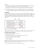
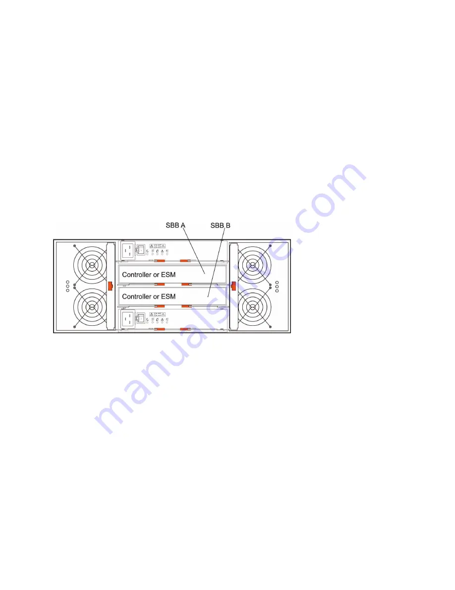
The DCS3700 storage system (1818-80C) comes with two hot-swappable and redundant controllers. The
controllers contain the storage subsystem control logic, interface ports, and LEDs. The controllers install
from the rear of the storage enclosure. Controller A is installed in storage bridge bay slot A (SBB A) and
controller B is installed in storage bridge bay slot B (SBB B). All connections to the hosts and the
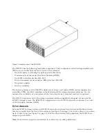
expansion enclosures are made through the controllers. Figure 4 shows the location of the controllers in
the DCS3700.
Information about the condition of the controllers is conveyed by indicator LEDs on the controller. See
“Controller LEDs” on page 74 for more information on the LEDs found on the RAID controller.
Controller cable connections
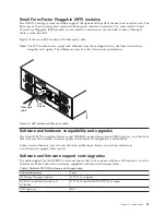
Each controller contains the following connections:
v
Two 6 Gbps x4 SAS host ports
v
One 6 Gbps x4 SAS expansion port to connect DCS3700 expansion enclosures
v
Two RJ-45 Ethernet ports for subsystem management
v
Support for one optional host interface card (HIC)
– Two-port 6 Gbps SAS
– Four-port 8 Gbps FC
Attention:
The DCS3700 storage system controllers must be identical to each other in hardware (host
port adapter and cache size) and firmware. If you install a host port adapter in one controller, you must
install an identical host port adapter in the other controller.
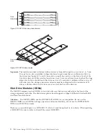
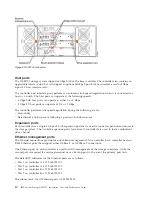
Figure 5 on page 10 identifies the connectors found on the controller.
Figure 4. Location of the DCS3700 controllers
Chapter 1. Introduction
9
Summary of Contents for DCS3700
Page 1: ...IBM System Storage DCS3700 Installation User and Maintenance Guide...
Page 2: ......
Page 3: ...IBM System Storage DCS3700 Installation User and Maintenance Guide...
Page 8: ...vi IBM System Storage DCS3700 Installation User and Maintenance Guide...
Page 12: ...x IBM System Storage DCS3700 Installation User and Maintenance Guide...
Page 18: ...xvi IBM System Storage DCS3700 Installation User and Maintenance Guide...
Page 22: ...xx IBM System Storage DCS3700 Installation User and Maintenance Guide...
Page 62: ...40 IBM System Storage DCS3700 Installation User and Maintenance Guide...
Page 75: ...Figure 34 Single Expansion Enclosures Chapter 3 Cabling the DCS3700 53...
Page 88: ...66 IBM System Storage DCS3700 Installation User and Maintenance Guide...
Page 150: ...128 IBM System Storage DCS3700 Installation User and Maintenance Guide...
Page 168: ...146 IBM System Storage DCS3700 Installation User and Maintenance Guide...
Page 178: ...156 IBM System Storage DCS3700 Installation User and Maintenance Guide...
Page 180: ...158 IBM System Storage DCS3700 Installation User and Maintenance Guide...
Page 188: ...166 IBM System Storage DCS3700 Installation User and Maintenance Guide...
Page 198: ...176 IBM System Storage DCS3700 Installation User and Maintenance Guide...
Page 201: ......
Page 202: ...Part Number 90Y8588 Printed in USA 1P P N 90Y8588...


