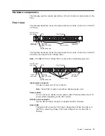


Operation
mode
DIP
switch
Sets
the
mode
of
operation
for
the
PDU.
The
default
mode
is
S1
off,
S2
off
for
normal
operation.
1=Off,
2=Off
The
card
will
run
normal
operational
firmware.
1=On,
2=On
The
card
will
start
in
diagnostics
mode.
1=On,
2=Off
Serial
upgrade
mode.
You
can
upgrade
the
PDU
firmware
from
the
serial
connection
if
the
network
upgrade
is
not
available.
1=Off
2=On
Read-only
mode.
The
device
will
run
normal
operational
firmware,
but
all
parameters
of
the
device
cannot
be
changed
by
a
user.
Reset
button
Resets
the
PDU
for
communication
purposes
only.
Resetting
the
PDU
does
not
affect
the
loads.
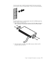
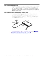
RJ-45
console
connector
Connect
the
DB9-to-RJ-45
cable
that
comes
with
the
PDU
to
this
connector
and
to
the
serial
(COM)
connector
on
a
workstation
or
notebook
computer
and
use
the
workstation
or
notebook
as
a
configuration
console.
You
can
also
connect
an
environmental
monitored
probe
to
this
connector.
The
environmental
monitored
probe
monitors
humidity
and
temperature.
The
connection
of
an
environmental
monitored
probe
is
automatically
detected.
Green
LED
(on
the
left
in
a
horizontal
orientation;
on
the
top
in
a
vertical
orientation):
v
This
LED
is
lit
when
the
device
is
powered
on.
v
This
LED
flashes
while
booting
to
indicate
startup
status.
Amber
LED
(on
the
right
in
a
horizontal
orientation;
on
the
bottom
in
a
vertical
orientation)):
v
This
LED
flashes
while
communicating
with
a
server
or
computer
or
when
reading
data
from
an
environmental
monitored
probe.
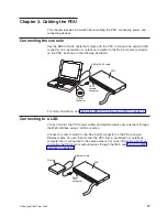
RJ-45
Ethernet
(LAN)
connector
Use
this
connector
to
configure
the
PDU
through
a
LAN.
The
Ethernet
connector
supports
10/100
auto
sense
network
connection.
Green
LED
(on
left):
v
This
LED
is
lit
when
connected
to
a
100
Mb
network.
v
This
LED
flashes
while
data
is
transmitted
and
received.
Amber
LED
(on
right):
v
This
LED
is
lit
when
connected
to
a
10
Mb
network.
v
This
LED
flashes
while
data
is
transmitted
and
received.
6
DPI
C13
PDU+,
DPI
C19
PDU+,
and
DPI
C19
3-phase
PDU+:
Installation
and
Maintenance
Guide
Summary of Contents for DPI C13 PDU+
Page 1: ...DPI C13 PDU DPI C19 PDU and DPI C19 3 phase PDU Installation and Maintenance Guide...
Page 2: ......
Page 3: ...DPI C13 PDU DPI C19 PDU and DPI C19 3 phase PDU Installation and Maintenance Guide...
Page 20: ...8 DPI C13 PDU DPI C19 PDU and DPI C19 3 phase PDU Installation and Maintenance Guide...
Page 28: ...16 DPI C13 PDU DPI C19 PDU and DPI C19 3 phase PDU Installation and Maintenance Guide...
Page 48: ...36 DPI C13 PDU DPI C19 PDU and DPI C19 3 phase PDU Installation and Maintenance Guide...
Page 54: ...42 DPI C13 PDU DPI C19 PDU and DPI C19 3 phase PDU Installation and Maintenance Guide...
Page 58: ...46 DPI C13 PDU DPI C19 PDU and DPI C19 3 phase PDU Installation and Maintenance Guide...
Page 87: ......
Page 88: ...Part Number 40K9635 Printed in USA 1P P N 40K9635...


