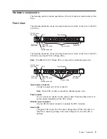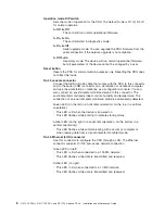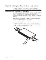
Rear
view
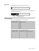
The
following
illustration
shows
the
rear
of
the
DPI
C13
PDU+.
The
following
illustration
shows
the
power
outlets
on
the
rear
of
the
DPI
C19
PDU+
and
the
DPI
C19
3-Phase
PDU+.
3A
1A
5A
C13
outlets
Labels indicating associated
breakers on the front of the PDU
PDU
load
groups
The
PDU
load
groups
are
described
in
the
following
tables.
Table
1.
DPI
C13
PDU+
load
groups
Circuit
breaker
number
Associated
front
outlets
1
1
and
2
2
3
and
4
3
5
and
6
4
7
and
8
5
9
and
10
6
11
and
12
Table
2.
DPI
C19
PDU+
and
DPI
C19
3-phase
PDU+
load
groups
Circuit
breaker
number
Associated
front
outlet
Associated
rear
outlet
1
1
1A
2
2
3
3
3A
4
4
5
5
5A
6
6
Chapter
1.
Introduction
7
Summary of Contents for DPI C13 PDU+
Page 1: ...DPI C13 PDU DPI C19 PDU and DPI C19 3 phase PDU Installation and Maintenance Guide...
Page 2: ......
Page 3: ...DPI C13 PDU DPI C19 PDU and DPI C19 3 phase PDU Installation and Maintenance Guide...
Page 20: ...8 DPI C13 PDU DPI C19 PDU and DPI C19 3 phase PDU Installation and Maintenance Guide...
Page 28: ...16 DPI C13 PDU DPI C19 PDU and DPI C19 3 phase PDU Installation and Maintenance Guide...
Page 48: ...36 DPI C13 PDU DPI C19 PDU and DPI C19 3 phase PDU Installation and Maintenance Guide...
Page 54: ...42 DPI C13 PDU DPI C19 PDU and DPI C19 3 phase PDU Installation and Maintenance Guide...
Page 58: ...46 DPI C13 PDU DPI C19 PDU and DPI C19 3 phase PDU Installation and Maintenance Guide...
Page 87: ......
Page 88: ...Part Number 40K9635 Printed in USA 1P P N 40K9635...

