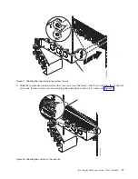
3.
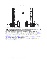
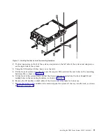
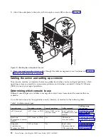
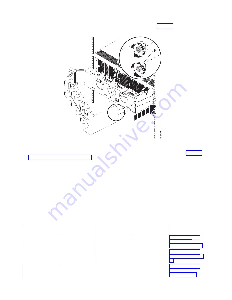
Attach the outer plate to the rails with two captive screws (E) as shown in Figure 19.
4.
Next, you must route the system cables through the cable management arm. Continue with “Cabling
the server and setting up a console.”
Cabling the server and setting up a console
Your console, monitor, or interface choices are guided by whether you create logical partitions, which
operating system you install in your primary partition, and whether you install a Virtual I/O Server
(VIOS) in one of your logical partitions.
Determining which console to use
Different console types are available to manage this server. Learn more about the consoles that are
available.
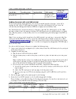
Go to the instructions for the applicable console, interface, or terminal in the following table.
Table 1. Available console types
Console type
Operating system
Logical partitions
Cable required
Cabling setup
instructions
ASCII terminal
AIX
®
, Linux, or VIOS
Yes for VIOS, no for
AIX and Linux
Serial cable that is
equipped with a null
modem
“Cabling the server
with an ASCII
terminal” on page 19
Hardware
Management Console
(HMC)
AIX, Linux, or VIOS
Yes
Ethernet (or
cross-over cable)
“Cabling the server
to the HMC” on page
20
Integrated
Virtualization
Manager for VIOS
AIX, or Linux
Yes
Serial cable /
Ethernet cable for
LAN connection
“Cabling the server
and accessing the
IVM” on page 21
Figure 19. Attaching the outer plate to the rails
18
Power Systems: Installing the IBM Power System E850C (8408-44E)
Summary of Contents for E850C
Page 1: ...Power Systems Installing the IBM Power System E850C 8408 44E GI11 9920 00 IBM...
Page 2: ......
Page 3: ...Power Systems Installing the IBM Power System E850C 8408 44E GI11 9920 00 IBM...
Page 6: ...iv Power Systems Installing the IBM Power System E850C 8408 44E...
Page 16: ...xiv Power Systems Installing the IBM Power System E850C 8408 44E...
Page 54: ...38 Power Systems Installing the IBM Power System E850C 8408 44E...
Page 67: ...Notices 51...
Page 68: ...IBM Part Number 29R2425 Printed in USA GI11 9920 00 1P P N 29R2425...

