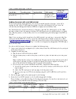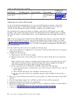
Table 3. Available console types (continued)
Console type
Operating system
Logical partitions
Cable required
Cabling setup
instructions
Keyboard, video, and
mouse (KVM)
Linux or VIOS
Yes
Monitor and USB
cables equipped with
KVM
“Cabling the server
with keyboard,
video, and mouse”
on page 33
Cabling the server with an ASCII terminal:
If you are not creating logical partitions, you can use an ASCII terminal to manage a server that is
running the AIX, Linux, or VIOS operating systems. From the ASCII terminal, you can access the
Advanced System Management Interface (ASMI) to complete more installation tasks.
The ASCII terminal is connected to the server through a serial link. The ASCII interface to the ASMI
provides a subset of the web interface functions. The ASCII terminal for the ASMI interface is available
only when the system is in the standby state. It is not available during the initial program load (IPL) or
run time.
Note:
If you are using a serial connection to the ASMI terminal, you must use a conversion cable. This
cable (part number 46K5108) is used to convert the ASCII terminal 9-pin Dshell connector to an RJ45
serial port connector on the system. For information about the locations of the connectors on the system,
see Part locations and location codes (http://www.ibm.com/support/knowledgecenter/POWER8/p8ecs/
p8ecs_locations.htm).
To cable an ASCII terminal to the server, complete the following steps:
1.
Using a serial cable that is equipped with a null modem, connect the ASCII terminal to the serial port
on the rear of the server.
2.
Complete the following steps:
a.
Plug the power cord into the power supply.
b.
Plug the system power cords and the power cords for any other attached devices into the power
source.
Note:
Confirm that the system is in standby mode. The green power status indicator on the front
control panel is flashing, and the dc out indicator lights on the power supplies are flashing. If
none of the indicators are flashing, check the power cord connections.
c.
If your system uses a power distribution unit (PDU), complete the following steps:
1)
Connect the system power cords from the server and I/O drawers to the PDU with an IEC 320
type receptacle.
2)
Attach the PDU input power cord and plug it into the power source.
3)
If your system uses two PDUs for redundancy, plug E1 and E2 to PDU A and E3 and E4 to
PDU B
.
3.
Press a key on the ASCII terminal to allow the service processor to confirm the presence of the ASCII
terminal.
4.
When the login display appears for the ASMI, enter
admin
for the user ID and password.
5.
Change the default password when you are prompted.
6.
Press Enter until the server information appears. You have completed the setup for an ASCII terminal,
and have started the ASMI.
7.
Continue with “Completing the server setup without using an HMC” on page 36.
30
Power Systems: Installing the IBM Power System E850C (8408-44E)
Summary of Contents for E850C
Page 1: ...Power Systems Installing the IBM Power System E850C 8408 44E GI11 9920 00 IBM...
Page 2: ......
Page 3: ...Power Systems Installing the IBM Power System E850C 8408 44E GI11 9920 00 IBM...
Page 6: ...iv Power Systems Installing the IBM Power System E850C 8408 44E...
Page 16: ...xiv Power Systems Installing the IBM Power System E850C 8408 44E...
Page 54: ...38 Power Systems Installing the IBM Power System E850C 8408 44E...
Page 67: ...Notices 51...
Page 68: ...IBM Part Number 29R2425 Printed in USA GI11 9920 00 1P P N 29R2425...

