48
IBM Power System E850C: Technical Overview and Introduction
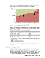
Figure 2-10 on page 46 shows the physical and logical placement of the slots.
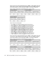
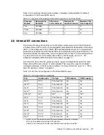
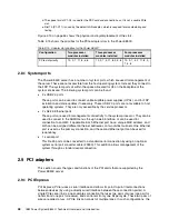
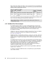
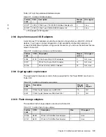
Table 2-15 shows the priorities for the PCIe adapter slots in the Power E850C.
Table 2-15 Adapter slot priorities for the Power E850C
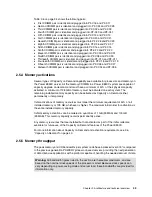
2.8.1 System ports
The Power E850C server has a number of system ports, which are used for management of
the server. These are not accessible from the host operating system. Instead, they connect to
the FSP. The system ports sit within the space allocated for C5 on the backplane of the
system enclosure. The following system ports can be found:
2 x USB 2.0 ports
These ports can be used to connect uninterruptible power supplies (UPSs), and for FSP
installation and code updates if necessary. These USB 2.0 ports are not available to host
operating systems. They are only accessible by the service processor.
2 x RJ-45 Ethernet ports
These ports are used for management connectivity to the system processor. They can be
used to connect to the ASMI menus through a web interface, or can be used for
connection to an HMC if applicable. Each Ethernet port has a unique MAC address, and
both can be assigned different Ethernet addresses on two distinct subnets. One Ethernet
port is used as the primary connection, and the second Ethernet port can be used for
redundancy.
1 x serial port
This RJ-45 port can be converted to a standard serial connection by using an optional
system serial port converter cable (#3930). This addition allows management of the
system through a standard serial connection.
2.9 PCI adapters
This section covers the types and functions of the PCI cards that are supported by the
Power E850C server.
2.9.1 PCI Express
PCI Express (PCIe) uses a serial interface and allows for point-to-point interconnections
between devices (by using a directly wired interface between these connection points). A
single PCIe serial link is a dual-simplex connection that uses two pairs of wires (one pair for
transmit and one pair for receive), and can transmit only one bit per cycle. These two pairs of
wires are called a
lane
. A PCIe link can consist of multiple lanes. In such configurations, the
d. The space for slot P1-C5 is used for the FSP card and connections, so it is not a usable PCIe
slot.
e. Slot 10 (P1-C11) is used by the default LAN adapter, which is required for manufacturing and
testing.
Configuration
Two processor
modules installed
Three processor
modules installed
Four processor
modules installed
PCIe slot priority
10, 9, 7, 11, 8, 5, 6
10, 9, 7, 4, 11, 8, 3, 5, 6
10, 9, 7, 4, 2, 11, 8, 3,
1, 5, 6
Summary of Contents for E850C
Page 2: ......
Page 36: ...22 IBM Power System E850C Technical Overview and Introduction...
Page 114: ...100 IBM Power System E850C Technical Overview and Introduction...
Page 154: ...140 IBM Power System E850C Technical Overview and Introduction...
Page 158: ...144 IBM Power System E850C Technical Overview and Introduction...
Page 159: ......
Page 160: ...ibm com redbooks Printed in U S A Back cover ISBN 0738455687 REDP 5412 00...

