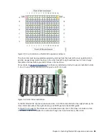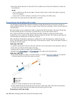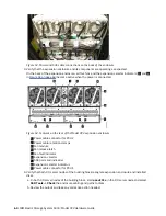
7. Connect the SAS cable to the SAS port with blue tab above the connector (that is, facing towards the
top of the node).
You hear or feel a click when the cable is successfully inserted. You cannot disconnect the cable
without pulling on the blue tag.
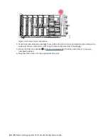
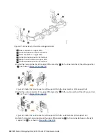
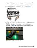
8. Route the SAS cables through the cable management arms, as shown in Figure 48 on page 61.
Figure 48. Example of SAS cables routed through the cable management arms
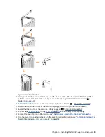
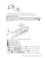
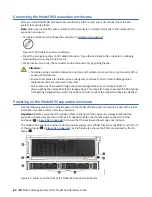
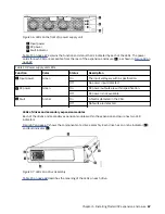
9. When both ends of a SAS cable are correctly connected, the green link-LED next to the connected SAS
ports are lit.
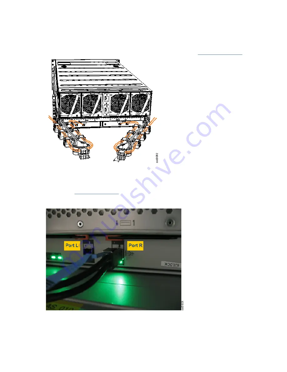
For example, Figure 49 on page 61 shows the LEDs of expansion canister 1 on a Model 092
expansion enclosure. The SAS cable is successfully inserted in to right port (input); left port (output)
does not contain a SAS cable.
Figure 49. SAS cable correctly inserted into the SAS port
Chapter 5. Installing Model 092 expansion enclosure 61
Summary of Contents for Elastic Storage System 5000 Series
Page 1: ...IBM Elastic Storage System 5000 Version 6 0 1 Model 092 Hardware Guide IBM SC28 3135 00...
Page 8: ...viii...
Page 10: ...24 Enclosure models and rack requirements 74 x...
Page 14: ...xiv IBM Elastic Storage System 5000 Model 092 Hardware Guide...
Page 32: ...18 IBM Elastic Storage System 5000 Model 092 Hardware Guide...
Page 36: ...22 IBM Elastic Storage System 5000 Model 092 Hardware Guide...
Page 51: ...Figure 11 Cable connectivity from I O servers Chapter 4 Planning for hardware 37...
Page 86: ...72 IBM Elastic Storage System 5000 Model 092 Hardware Guide...
Page 90: ...76 IBM Elastic Storage System 5000 Model 092 Hardware Guide...
Page 98: ...84 IBM Elastic Storage System 5000 Model 092 Hardware Guide...
Page 100: ...86 IBM Elastic Storage System 5000 Model 092 Hardware Guide...
Page 101: ......
Page 102: ...IBM Product Number 5765 DME 5765 DAE SC28 3135 00...

