background image

Reviewing Model 092 expansion enclosure location guidelines

Consult these guidelines when you plan the location of Model 092 expansion enclosure and any existing

Elastic Storage System in your environment, including any IBM Spectrum Scale client or protocol node.
Each ESS 5000 cluster consists of the following components:
• One or more ESS 5000 building blocks. Each building block is composed of two I/O server nodes. Each

I/O server node requires 2U (standard rack units) space in a rack. The I/O server nodes are attached to

up to six Model 092 expansion enclosures.

• One ESS Management Server (EMS) node. The EMS node requires 2U space in a rack. The EMS can

support several ESS 5000 building blocks.

Planning for power for Model 092 expansion enclosure

Each Model 092 expansion enclosure is provided power through two power supply units (PSU). Either of

the power supply units can power the enclosure independently if there is a loss of input power to the

other power supply in the enclosure.
Plan to connect the power cords of the power supplies on the left side of the enclosures (when viewed

from the rear) to one power source, and connect the power cords of the power supplies on the right side

of the enclosures to another power source.

Attention: The power cord is the main power disconnect. Ensure that the socket outlets are

located near the equipment and are easily accessible.

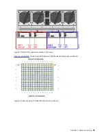
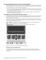
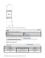
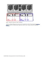
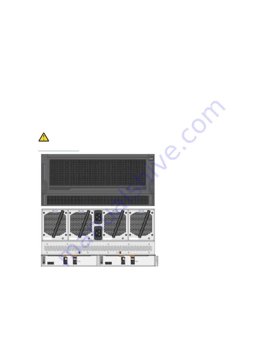
Figure 5 on page 24 shows the front and the rear of a Model 092 expansion enclosure. 

Figure 5. Front and rear view of Model 092 expansion enclosure

Planning for cable connections to PDUs
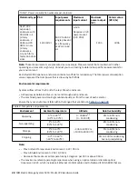
Each Model 092 expansion enclosure must be connected to a pair of power outlets by selecting

appropriate feature codes while ordering the system. The following table lists the feature codes of the

power cords:

24  IBM Elastic Storage System 5000: Model 092 Hardware Guide

Summary of Contents for Elastic Storage System 5000 Series

Page 1: ...IBM Elastic Storage System 5000 Version 6 0 1 Model 092 Hardware Guide IBM SC28 3135 00...

Page 2: ...roduct number 5765 DME IBM Spectrum Scale Data Access Edition for IBM ESS product number 5765 DAE IBM welcomes your comments see the topic How to submit your comments on page xiii When you send inform...

Page 3: ...Interference VCCI Notice 13 Korea Notice 13 People s Republic of China Notice 13 Russia Notice 13 Taiwan Notice 14 United States Federal Communications Commission FCC Notice 14 Chapter 2 Weight consid...

Page 4: ...er 54 Installing or replacing a Model 092 expansion enclosure in a rack 55 Installing or replacing the cable management arms 56 Removing and installing a SAS cable 60 Connecting the Model 092 expansio...

Page 5: ...ion enclosures 35 9 SAS host bus adapters 35 10 Location of SAS host bus adapters 36 11 Cable connectivity from I O servers 37 12 Tray containing expansion enclosure parts 40 13 Packaging materials 40...

Page 6: ...top cover 54 37 Locking the top cover 55 38 Example installation of the enclosure in the rack 55 39 Replacing the Model 092 enclosure in the rack 56 40 Upper and lower cable management arms 57 41 Uppe...

Page 7: ...SAS cable connections on the back of the enclosure 64 54 Features on the rear of the Model 092 expansion enclosure 64 55 LEDs on the front of the expansion enclosure 66 56 LEDs on the front of a powe...

Page 8: ...viii...

Page 9: ...10 Rack space requirements for the Model 092 expansion enclosure 29 11 Service clearance requirements 30 12 Clearances 30 13 Drive specifications 31 14 Acoustical noise emissions 31 15 Declared noise...

Page 10: ...24 Enclosure models and rack requirements 74 x...

Page 11: ...cluding initial hardware installation and setup and removal and installation of field replaceable units FRUs customer replaceable units CRUs for ESS 5000 Expansion Model 092 5147 092 System administra...

Page 12: ...ppear in constant width typeface Depending on the context constant width typeface sometimes represents path names directories or file names italic Italic words or characters represent variable values...

Page 13: ...other words a vertical line means Or In the left margin of the document vertical lines indicate technical changes to the information How to submit your comments To contact the IBM Spectrum Scale devel...

Page 14: ...xiv IBM Elastic Storage System 5000 Model 092 Hardware Guide...

Page 15: ...IBM Japan Ltd 19 21 Nihonbashi Hakozakicho Chuo ku Tokyo 103 8510 Japan INTERNATIONAL BUSINESS MACHINES CORPORATION PROVIDES THIS PUBLICATION AS IS WITHOUT WARRANTY OF ANY KIND EITHER EXPRESS OR IMPL...

Page 16: ...ms in source language which illustrate programming techniques on various operating platforms You may copy modify and distribute these sample programs in any form without payment to IBM for the purpose...

Page 17: ...2 Locate the IBM Systems Safety Notices with the user publications that were provided with your system hardware 3 Find the matching identification number in the IBM Systems Safety Notices Then review...

Page 18: ...tion notice or each danger notice In the following examples the numbers D002 and C001 are the identification numbers DANGER A danger notice indicates the presence of a hazard that has the potential of...

Page 19: ...ce hazardous voltage on the metal parts of the system or the devices that attach to the system It is the responsibility of the customer to ensure that the outlet is correctly wired and grounded to pre...

Page 20: ...es shelves drawers doors and cables are secure Ensure that the four leveling pads are raised to their highest position Ensure that there is no stabilizer bracket installed on the rack cabinet during m...

Page 21: ...rvices must be used for instance riggers or movers Read and completely understand the contents of LIFT TOOL operator s manual before using Read and completely understand the contents of LIFT TOOL oper...

Page 22: ...f 2 CAUTION If the System slide rails are installed above EIA location 29U the ServerLIFT tool or other qualified lift tool must be used as a safety precaution for servicing Position the lift tool pla...

Page 23: ...spection make sure that the power is off and that the power cord is disconnected Each device has the required safety items that are installed to protect users and support personnel from injury Only th...

Page 24: ...hanges that were made to the device 2 Check the condition of the inside of the device for any metal or other contaminants or any indications of water other fluid fire or smoke damage 3 Check for any o...

Page 25: ...g of non IBM option cards This product may cause interference if used in residential areas Such use must be avoided unless the user takes special measures to reduce electromagnetic emissions to preven...

Page 26: ...Business Machines Corp New Orchard Road Armonk New York 10504 Tel 914 499 1900 Der verantwortliche Ansprechpartner des Herstellers in der EU ist IBM Deutschland GmbH Technical Relations Europe Abteil...

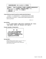
Page 27: ...Japan Voluntary Control Council for Interference VCCI Notice Korea Notice People s Republic of China Notice Russia Notice Chapter 1 Notices 13...

Page 28: ...rrect the interference at his own expense Properly shielded and grounded cables and connectors must be used in order to meet FCC emission limits IBM is not responsible for any radio or television inte...

Page 29: ...ree persons are required to move the enclosure while it is in the rack if you are moving the enclosure off the rails Even after the drives power supply units secondary expander modules canisters fans...

Page 30: ...B 2 5 inch SSD 0 224 0 494 6 TB 3 5 inch HDD 0 876 1 931 10 TB 3 5 inch HDD 0 876 1 931 14 TB 3 5 inch HDD 0 876 1 931 16 TB 3 5 inch HDD 0 670 1 477 Weight increases as FRUs are installed As you inst...

Page 31: ...enclosure is initially shipped Enclosure Secondary expansion modules PSUs Expansion canisters Fan modules Fan interface board Display assembly Cover Fascia 1U and 4U Drives 61 5 135 4 Enclosure Second...

Page 32: ...18 IBM Elastic Storage System 5000 Model 092 Hardware Guide...

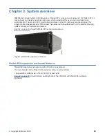
Page 33: ...lows the enclosure to be withdrawn from the rack for servicing while remaining connected and powered Figure 1 on page 19 shows the Model 092 expansion enclosure Figure 1 Model 092 expansion enclosure...

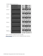
Page 34: ...Figure 2 ESS 5000 with Model 092 expansion enclosure Figure 3 on page 21 shows the rear view of a Model 092 expansion enclosure 20 IBM Elastic Storage System 5000 Model 092 Hardware Guide...

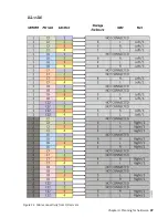
Page 35: ...Model 092 expansion enclosure rear view Figure 4 on page 21 shows the disk locations in the Model 092 expansion enclosure Figure 4 Drive locations of Model 092 expansion enclosure Chapter 3 System ove...

Page 36: ...22 IBM Elastic Storage System 5000 Model 092 Hardware Guide...

Page 37: ...are installation Before the IBM SSR installs the system you must plan the physical configuration and the initial data configuration Certain physical site specifications must be met before you can set...

Page 38: ...ower supply units PSU Either of the power supply units can power the enclosure independently if there is a loss of input power to the other power supply in the enclosure Plan to connect the power cord...

Page 39: ...n enclosure Do the power circuits you are planning to use have sufficient capacity and the correct sockets for your installation A clearly visible and accessible emergency power off switch is required...

Page 40: ...hazardous voltage on the metal parts of the system or the devices that attach to the system It is the responsibility of the customer to ensure that the outlet is correctly wired and grounded to preven...

Page 41: ...trical distribution system It must provide overcurrent protection for the enclosure and must not be overloaded by the total number of enclosures installed The electrical power consumption rating that...

Page 42: ...of each enclosure Airflow passes between drive carriers and through each enclosure The combined power and cooling module exhausts air from the rear of each canister Ensure that your environment falls...

Page 43: ...damage during transport and subsequent loss of data see Procedure Transporting a 5U 92 drive expansion enclosure The procedure describes what to do for the following situations When you are powering o...

Page 44: ...layout of the room see Computer room layout See Site preparation and physical planning section to help you prepare your physical site for the installation of a Model 092 expansion enclosure Additiona...

Page 45: ...orted in conformance with ISO 9296 Table 14 Acoustical noise emissions Enclosure type Drive configuration Acoustical output per enclosure Idling Operating Expansion enclosure 90 LFF drives 6 1 bels 6...

Page 46: ...nstalled the noise levels from other equipment the room ambient temperature and employees location in relation to the equipment Further compliance with such government regulations also depends upon a...

Page 47: ...D For further customization see IBM Spectrum Scale RAID Administration guide Planning the network and storage network Plan to provide the network infrastructure and the storage network infrastructure...

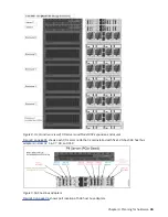
Page 48: ...n Model 092 expansion enclosures can be attached to an ESS 5000 building block Figure 8 on page 35 shows the front left and rear right view of the I O server nodes and Model 092 expansion enclosures 3...

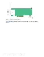
Page 49: ...ures Figure 9 on page 35 shows each I O server node that is preinstalled with five 12 Gbps SAS host bus adapters in slots C2 C6 C7 C8 and C12 Figure 9 SAS host bus adapters Figure 10 on page 36 shows...

Page 50: ...re 10 Location of SAS host bus adapters Figure 11 on page 37 shows cable connectivity from I O server nodes to the Model 092 expansion enclosure 36 IBM Elastic Storage System 5000 Model 092 Hardware G...

Page 51: ...Figure 11 Cable connectivity from I O servers Chapter 4 Planning for hardware 37...

Page 52: ...ut the supported environment for your system Environmental topics can include updates about the following items Host attachments Physical disk storage systems Host bus adapters Switches Firmware level...

Page 53: ...nclosure ensure that you review and follow the installation checklist and the safety notices CAUTION The weight of this part or unit is more than 55 kg 121 2 lb It takes specially trained persons a li...

Page 54: ...Note Drives are not included in installation package for the enclosure they are provided in a separate package 1 Remove the cardboard tray that contains the slide rails cable management arm and fasci...

Page 55: ...092 expansion enclosure in a rack on page 55 11 Remove the 4U fascia and the 1U fascia from the boxes in which they were shipped as shown in Figure 14 on page 41 Figure 14 Packaging for fascia 1 4U f...

Page 56: ...es on the front of the Model 092 expansion enclosure 1 Display panel indicators 2 Rack retention thumb screws 3 Power supply unit indicators 4 Power supply units PSUs 5 PSU fascia 1U 6 Front fascia 4U...

Page 57: ...enclosure 1 Power cable connector for PSU 2 2 Power cable retention clamps 3 Fan module 4 Fan release latch 5 Fan fault indicator 6 Expansion canister 7 SAS ports and indicators 8 Expansion canister...

Page 58: ...t powering off the expansion enclosure However to maintain operating temperature replace the cover within 15 minutes of its removal When the cover is removed the reduction in airflow through the enclo...

Page 59: ...rack location ensure that the enclosure and its parts are easily accessible Allow enough space for the lid to be easily removed and for internal components such as drives and secondary expansion modu...

Page 60: ...attach the inner rail to the enclosure 5 Install the inner section of the rail onto each side of the expansion enclosure as shown in Figure 25 on page 46 Figure 25 Attaching the inner rail section to...

Page 61: ...o the frame Figure 27 Example of the required rack space 7 Repeat steps 5 on page 46 through 6 on page 46 to install the opposite rail 8 Install the expansion enclosure in the rack For more informatio...

Page 62: ...ocess Attach the front 4U fascia 1 Align the front 4U fascia with the enclosure so that the thumbscrews go through the holes on each side As Figure 29 on page 49 shows this action aligns the screw hol...

Page 63: ...ailed disks are in the replaceable status they can be replaced by using corresponding directed maintenance procedure Select Replace Broken Disks from the Actions menu in the Monitoring Hardware window...

Page 64: ...ator is lit 3 in Figure 30 on page 50 Do not replace a drive unless the drive fault indicator is on or you are instructed to do so by a fix procedure A label on the enclosure cover Figure 31 on page 5...

Page 65: ...are installed correctly Drives are installed in slots 1 14 of row A and the installation continues in slot 15 in row B Figure 32 Correct drive installation In the first Model 092 expansion enclosure...

Page 66: ...surface on the enclosure Wear an anti static wrist strap to remove the drive from the package 5 Ensure that the drive handle 1 in Figure 34 on page 53 of the drive assembly is in the open unlocked pos...

Page 67: ...oe on the bottom of the latch is fully engaged with the partition in the chassis 10 Ensure that the top toe of the latch is also fully engaged 4 in Figure 34 on page 53 11 Repeat steps 4 on page 52 th...

Page 68: ...he top cover on the Model 092 expansion enclosure complete the following steps 1 Carefully lower the cover and ensure that it is aligned correctly with the back of the enclosure as shown in Figure 35...

Page 69: ...drives power supply units secondary expander modules canisters fans and top cover are removed the enclosure weighs approximately 43 kg 95 lbs Install the expansion enclosure in the lowest position in...

Page 70: ...tabs near the front of the enclosure Press both release tabs forward to unlock the drawer mechanism 3 in Figure 39 on page 56 5 Push the enclosure firmly into the rack 4 in Figure 39 on page 56 6 Tigh...

Page 71: ...ail hooks at the end of the support rails Figure 41 Upper and lower cable management arms 1 Remove the loop straps from the upper and lower CMA assemblies The straps are used only for shipping Install...

Page 72: ...as shown in Figure 43 on page 58 Figure 43 Install the inner connector of the upper CMA to the inner member of the support rail 3 Install the outer connector of the upper CMA assembly 3 to the outer...

Page 73: ...g the location of the components of the CMA assemblies 7 Inner connector on lower CMA 8 Connector base on inner rail member 9 Outer connector on lower CMA 10 Connector base on outer rail member 11 Sup...

Page 74: ...cables The system cannot operate if the SAS cabling to the expansion enclosure is incorrect When the Model 092 expansion enclosure is installed in the rack the expansion canisters are upside down The...

Page 75: ...on page 61 Figure 48 Example of SAS cables routed through the cable management arms 9 When both ends of a SAS cable are correctly connected the green link LED next to the connected SAS ports are lit F...

Page 76: ...es must be routed through the cable management arms to reduce the risk of disconnecting the nodes from their storage arrays This step also helps to protect the SAS cables from getting damaged if you s...

Page 77: ...losure The enclosure automatically powers on and begins its Power On Self Tests POST 2 Secure the power cables in the cable retainer at each power connector on the rear of the enclosure as shown in Fi...

Page 78: ...connector for PSU 2 2 Power cable retention clamps 3 Fan module 4 Fan release latch 5 Fan fault indicator 6 Expansion canister 7 SAS ports and indicators 8 Expansion canister indicators 9 Power cable...

Page 79: ...from the enclosure unplug both power cords from the rear of the expansion enclosure Transporting a Model 092 expansion enclosure To transport an expansion enclosure or an entire rack that contains on...

Page 80: ...panel LEDs Function Color Status Description Power Green On The expansion enclosure power is on this LED is controlled by the expansion enclosure Off The expansion enclosure power is off Identify Blu...

Page 81: ...ation Off No power input detected 2 DC power Green On DC power outputs are within specification Off DC power is not available 3 Fault Amber On A fault is detected in the PSU Off No faults are detected...

Page 82: ...1 Online indicator 2 Fault indicator Table 21 on page 68 describes the meaning of the LEDs on each secondary expansion module Table 21 LED indicators on secondary expansion modules Function Color Stat...

Page 83: ...about the expansion canister itself and the SAS connections Figure 60 LEDs on the back of the expansion canister 1 Canister fault 2 Canister status 3 Canister power 4 and 6 SAS link fault 5 and 7 SAS...

Page 84: ...r conditions are possible Only 1 2 or 3 phys are connected but not all 4 The phys are not operating at the same speed All phys are not connected to the same remote port One or more of the connected la...

Page 85: ...to determine the extent to which you can attempt to accomplish any IBM ESS 5000 system maintenance IBM service support representatives and lab based services personnel can access service information t...

Page 86: ...72 IBM Elastic Storage System 5000 Model 092 Hardware Guide...

Page 87: ...hardware location chart represents the rack into which the enclosures are installed Each row of the chart represents one Electronic Industries Alliance EIA 19 inch wide by 1 75 inch tall rack space or...

Page 88: ...EIA 6 EIA 5 EIA 4 EIA 3 EIA 2 EIA 1 Table 24 on page 74 lists the rack requirements for a Model 092 expansion enclosure Table 24 Enclosure models and rack requirements Device Machine type and model Nu...

Page 89: ...by touch but do not activate just by touching them Industry standard devices for ports and connectors The attachment of alternative input and output devices IBM Knowledge Center and its related publi...

Page 90: ...76 IBM Elastic Storage System 5000 Model 092 Hardware Guide...

Page 91: ...e central processor complex CPC central processor complex CPC A physical collection of hardware that consists of channels timers main storage and one or more central processors cluster A loosely coupl...

Page 92: ...composed of one or more building blocks encryption key A mathematical value that allows components to verify that they are in communication with the expected server Encryption keys are based on a pub...

Page 93: ...as a unit for balancing workload across a cluster See also dependent fileset independent fileset fileset snapshot A snapshot of an independent fileset plus all dependent filesets flexible service proc...

Page 94: ...IP See Internet Protocol IP IP over InfiniBand IPoIB Provides an IP network emulation layer on top of InfiniBand RDMA networks which allows existing applications to run over InfiniBand networks unmodi...

Page 95: ...unit MTU N Network File System NFS A protocol developed by Sun Microsystems Incorporated that allows any host in a network to gain access to another host or netgroup and their file directories Networ...

Page 96: ...ta when a failure has occurred Recovery can involve reconstructing data or providing alternative routing through a different server recovery group RG A collection of disks that is set up by ESS in whi...

Page 97: ...n that results from them SSH See secure shell SSH STP See Spanning Tree Protocol STP symmetric multiprocessing SMP A computer architecture that provides fast performance by making multiple processors...

Page 98: ...84 IBM Elastic Storage System 5000 Model 092 Hardware Guide...

Page 99: ...h availability 33 homologation statement 3 I information overview xi inspections safety external device check 10 interfaces 25 L location guidelines enclosure 24 N notices environmental 11 O overview...

Page 100: ...86 IBM Elastic Storage System 5000 Model 092 Hardware Guide...

Page 101: ......

Page 102: ...IBM Product Number 5765 DME 5765 DAE SC28 3135 00...

Reviews: