EM78M611E
Universal Serial Bus Series Microcontroller
24
••••
Product Specification (V1.1) 11.22.2006
(This specification is subject to change without further notice)
:
// Set the Port 6 to input port
MOV A, @0xFF
IOW PORT6
// Read the state of Port 6
MOV PORT6, PORT6
// Clear the RUN bit
IOR 0xE
AND A, 0B11101111
IOW 0xE
:
:
8.7.2 Dual Clock Mode
The EM78M611E has one internal oscillator for power saving application. Clearing the
Bit IOCE [7] will enable the low frequency oscillator. At the same time, the external
oscillator will be turned off. Then the MCU will run under very low frequency to
conserve power. Four types of frequency are available for selection in setting bits
IOCA [6, 7].
The USB Host Resume Interrupt can only be used in this mode. If this interrupt is
enabled, the MCU will be interrupted when the USB Host Resume signal is detected on
USB Bus.
8.8 Interrupt
The EM78M611E has one interrupt vector in 0x0001. When an interrupt occurs during
an MCU program run, it will jump to the interrupt vector (0x0001) and execute the
instructions sequentially from the interrupt vector. RF is the interrupt status register,
which records the interrupt status in the relative flags/bits.
The interrupt condition could be one of the following:
TCC Overflow: When the Timer Clock / Counter Register (R1) overflows, the status flag
RF[0] will be set to 1. Its interrupt vector is 0X0001.
Port 7 State Change: When the input signals in Port 7 changes, the status flag RF[4]
will be set to 1. Its interrupt vector is 0X0001.
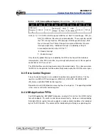
SE1 Pattern Detection Interrupt Conditions: If the Pattern Detection Application
function is enabled, there will be four conditions with which interrupt is generated,
and the status flag RF[5] is set to 1 (interrupt vector is 0X0001).
a) Signal from P.92 changes to low and the Pattern Counter value is bigger than
R11 register value.

