background image


Chapter 2.  Installing options

 19

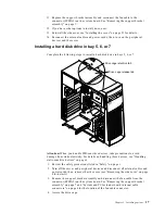
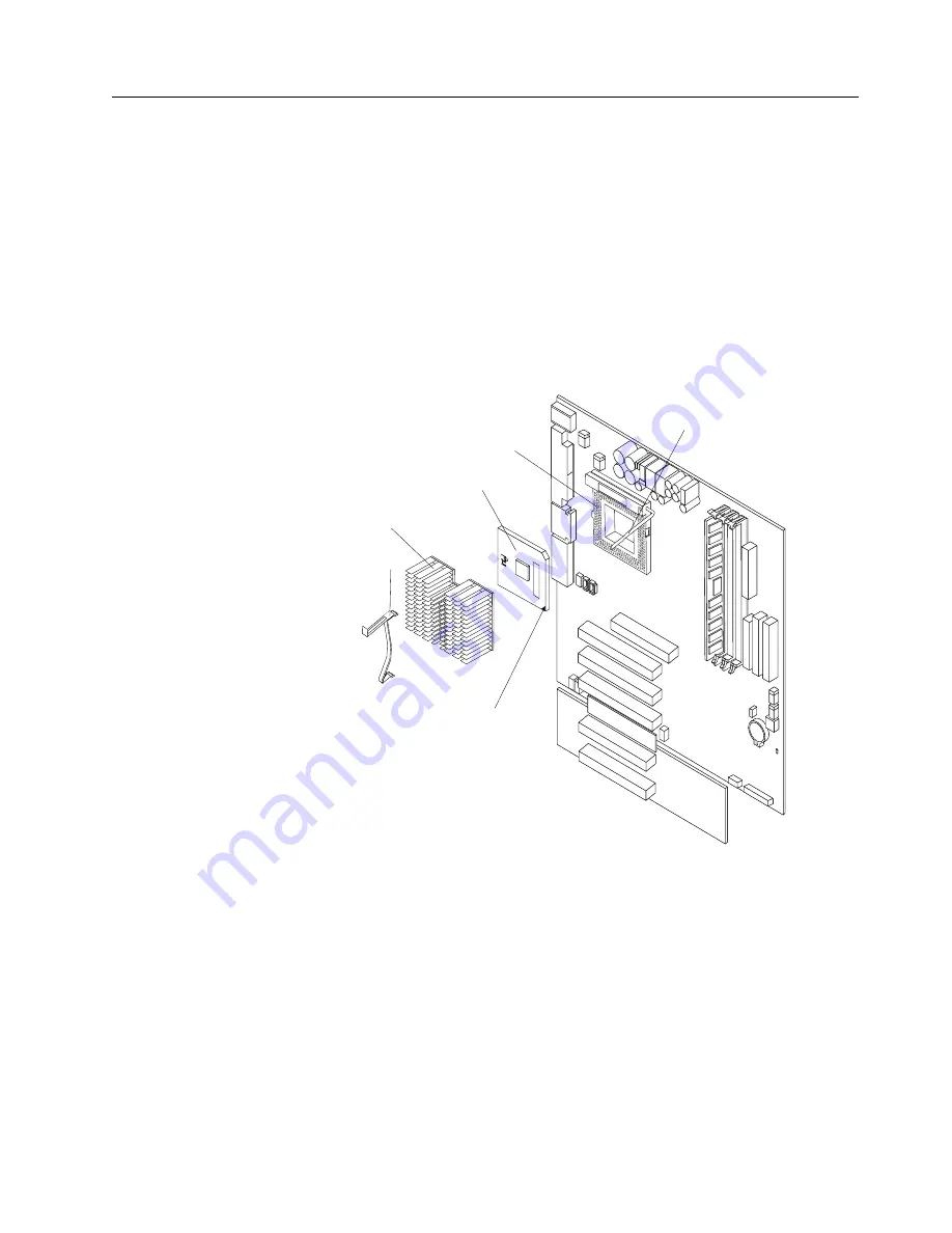
Removing and installing a microprocessor

Your server comes with one microprocessor installed on the system board in the 
microprocessor connector (U5). 

Notes:

1. Before you install a new microprocessor, review the documentation that comes 

with the microprocessor to determine whether you need to update the server 
BIOS code. The latest level of the BIOS code for your server is available through 
the World Wide Web.

2. The illustrations in this document might differ slightly from your hardware.

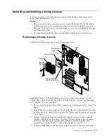
Removing a microprocessor

Complete the following steps to remove a microprocessor.

Attention: 

 When you handle ESD-sensitive devices, take precautions to avoid 

damage from static electricity. For details on handling these devices, see “Handling 
static-sensitive devices” on page x.

1. Review the safety precautions listed in Statement 1 and Statement 5 in “Safety” on 

page v.

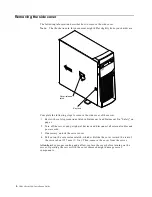
2. Turn off the server and peripheral devices and disconnect all external cables and 

power cords; then, remove the side cover (see “Removing the side cover” on page 
6 for details).

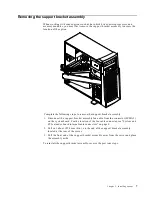
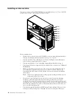
3. Remove the support bracket assembly and disconnect the fan cable from the 

connector (SYSFA3) on the system board. See “Removing the support bracket 
assembly” on page 7 and “System and PCI extender board internal cable 
connectors” on page 4 for the location of the fan cable connector.

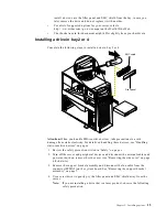
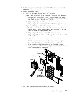
4. Push down and back on the heat-sink retainer to remove it from the heat sink.

Microprocessor

Microprocessor
connector

Microprocessor
orientation indicator

Lever

Heat sink

retainer

Heat sink

Summary of Contents for eServer 200 xSeries

Page 1: ...e server and options Start the server Install the server in the rack if required Did the server start correctly Yes No Use ServerGuide to setup and configure hardware Did configuration complete Use Se...

Page 2: ...bleshooting information provided with your server to determine the cause of the problem and the action to take Flash the latest levels of BIOS service processor diagnostics and RAID code You can downl...

Page 3: ...IBM IBM xSeries 200 Installation Guide SC06 P458 90...

Page 4: ...formation in Appendix A Product warranties and notices on page 33 First Edition October 2000 Copyright International Business Machines Corporation 2000 All rights reserved US Government Users Restrict...

Page 5: ...ver 25 Turning off the server 25 Server controls and indicators 26 Chapter 4 Configuring your server 27 Using the ServerGuide CDs 27 Chapter 5 Solving problems 29 Diagnostic tools overview 29 POST bee...

Page 6: ...iv IBM xSeries 200 Installation Guide...

Page 7: ...irjanen ennen kuin asennat t m n tuotteen Avant de proc der l installation de ce produit lisez le manuel Safety Information Vor Beginn der Installation die Brosch re mit Sicherheitshinweisen lesen Pri...

Page 8: ...instalar este produto leia o folheto Informa es sobre Seguran a Antes de instalar este producto lea la Informaci n de Seguridad L s s kerhetsinformationen innan du installerar den h r produkten Safety...

Page 9: ...on any equipment when there is evidence of fire water or structural damage Disconnect the attached power cords telecommunications systems networks and modems before you open the device covers unless i...

Page 10: ...equired by local ordinances or regulations Statement 3 CAUTION When laser products such as CD ROMs DVD drives fiber optic devices or transmitters are installed note the following Do not remove the cov...

Page 11: ...AUTION The power control button on the device and the power switch on the power supply do not turn off the electrical current supplied to the device The device also might have more than one power cord...

Page 12: ...ted circuitry Do not leave the device where others can handle and possibly damage the device While the device is still in its anti static package touch it to an unpainted metal part of the system unit...

Page 13: ...el and other IBM server products at the following World Wide Web address http www ibm com eserver xseries The server model and serial numbers are located on labels on the bottom of the server and on t...

Page 14: ...P video adapter Compatible with SVGA and VGA 8 MB SDRAM video memory Size Height 470 mm 18 5 in Depth 508 mm 19 9 in Width 165 mm 6 5 in Weight approximately 19 5 Kg 43 lb when fully configured or 15...

Page 15: ...ice is placed just before the instruction or situation in which damage could occur Caution These notices indicate situations that can be potentially hazardous to you A caution notice is placed just be...

Page 16: ...The following illustration identifies system and extender board connectors for internal cables System fan 2 SYSFA2 Support bracket assembly fan SYSFA3 Microprocessor fan sink CPUFA1 Secondary IDE IDE...

Page 17: ...ence on the IBM xSeries Documentation CD Moving the stabilizing feet The two front feet attached to the bottom of the server rotate 90 degrees to provide additional stability When you need to access t...

Page 18: ...ent 1 and Statement 5 in Safety on page v 2 Turn off the server and peripheral devices and disconnect all external cables and power cords 3 If necessary unlock the server cover 4 Pull out on the cover...

Page 19: ...et assembly 1 Disconnect the support bracket assembly fan cable from the connector SYSFA3 on the system board For the location of the fan cable connector see System and PCI extender board internal cab...

Page 20: ...V and universal PCI adapters it does not support 3 3V adapters Your server uses a rotational interrupt technique to configure PCI adapters Because of this technique you can install a variety of PCI ad...

Page 21: ...sion slot you will use for the adapter Note Check the instructions that come with the adapter for any requirements restrictions or cabling instructions It might be easier for you to route any cables b...

Page 22: ...er in the server be sure that it is completely and correctly seated in the PCI expansion slot before you turn on the server Incomplete insertion might cause damage to the system board or the adapter 1...

Page 23: ...connectors on page 4 for the location of this connector Note If you are installing a ServeRAID adapter and already have a SCSI adapter installed remove the SCSI adapter and store it for future use 4 I...

Page 24: ...information in the server Therefore after installing or removing a DIMM you must change and save the new configuration information by using the Configuration Setup Utility program When you restart the...

Page 25: ...gn correctly with the connector Attention To avoid breaking the retaining clips or damaging the DIMM connectors open and close the clips gently c Insert the DIMM into the connector by aligning the DIM...

Page 26: ...must attach the 5 25 in conversion kit supplied with your option to the 3 5 in drive Refer to the documentation that comes with the option for the conversion kit installation instructions Note Only 3...

Page 27: ...amage from static electricity For details on handling these devices see Handling static sensitive devices on page x 1 Review the safety precautions listed in Safety on page v 2 Turn off the server and...

Page 28: ...have a SCSI adapter installed Plug one connector of the SCSI signal cable into the back of the drive and the other end of the cable into the connector on the SCSI adapter See Installing an adapter on...

Page 29: ...ou handle ESD sensitive devices take precautions to avoid damage from static electricity For details on handling these devices see Handling static sensitive devices on page x 1 Review the safety preca...

Page 30: ...ive cage up and press in on the drive cage release tab then rotate the drive cage back into the server Note Clear any cables that might impede the replacement of the drive cage 8 Connect the signal an...

Page 31: ...ns to avoid damage from static electricity For details on handling these devices see Handling static sensitive devices on page x 1 Review the safety precautions listed in Statement 1 and Statement 5 i...

Page 32: ...Statement 5 in Safety on page v 2 Turn off the server and peripheral devices and disconnect all external cables and power cords then remove the side cover see Removing the side cover on page 6 for de...

Page 33: ...e plastic protective strip off the bottom of the fan sink Make sure that the square of thermal material is still on the bottom of the fan sink if not replace the fan sink with a new one b Align and pl...

Page 34: ...on the peripheral devices and the server Installing a security U bolt To help prevent hardware theft you can add a security U bolt and cable to your server After you add the security cable make sure...

Page 35: ...Installing the cover 6 Thread the cable through the U bolt and around an object that is a part of or permanently secured to the building structure or foundation and from which it cannot be removed th...

Page 36: ...t the external cables and power cords to the server and then plug the power cords into electrical outlets 6 Turn on the peripheral devices then turn on the server Cabling the server Note The illustrat...

Page 37: ...arts an orderly shutdown of the operating system if this feature is supported by your operating system and places the server in standby mode Note After turning off the server wait at least five second...

Page 38: ...et speed is 100 Mbps When the light is off the Ethernet speed is 10 Mbps Ethernet transmit receive activity When this light is on there is activity between the server and the network The Ethernet tran...

Page 39: ...guration conflicts and perform a low level format on a SCSI hard disk drive ServeRAID programs The ServeRAID programs come with the optional ServeRAID adapters and with server models that have a Serve...

Page 40: ...28 IBM xSeries 200 Installation Guide Note For information on the supported NOS versions refer to the Setup and Installation CD label...

Page 41: ...stic programs Troubleshooting chart This chart lists problem symptoms and steps to correct the problems See the Troubleshooting chart on page 31 for more information Customized support page You can cr...

Page 42: ...an one CD ROM drive is installed be sure that only one drive is set as the primary drive Start the CD from the primary drive ServeRAID program cannot view all installed drives or cannot install NOS En...

Page 43: ...th your monitor refer to the information that comes with the monitor for adjusting and testing instructions If the items above are correct and the screen remains blank call for service Wavy unreadable...

Page 44: ...y disabled a DIMM bank if it detected a problem or a DIMM bank could have been manually disabled If the problem persists call for service Option Suggested action An IBM option that was just installed...

Page 45: ...for your use and not for resale from IBM or your reseller The term Machine means an IBM machine its features conversions upgrades elements or accessories or any combination of them The term Machine do...

Page 46: ...IES OR CONDITIONS OF MERCHANTABILITY AND FITNESS FOR A PARTICULAR PURPOSE THESE WARRANTIES GIVE YOU SPECIFIC LEGAL RIGHTS AND YOU MAY ALSO HAVE OTHER RIGHTS WHICH VARY FROM JURISDICTION TO JURISDICTIO...

Page 47: ...nform IBM or your reseller of changes in a Machine s location IBM is responsible for loss of or damage to your Machine while it is 1 in IBM s possession or 2 in transit in those cases where IBM is res...

Page 48: ...nsumers that cannot be waived or limited by contract If you have any questions contact IBM or your reseller The IBM Warranty for Machines IBM warrants that each Machine 1 is free from defects in mater...

Page 49: ...either at your location or at a service center to keep Machines in or restore them to conformance with their Specifications IBM or your reseller will inform you of the available types of service for a...

Page 50: ...ed to claim damages from IBM including fundamental breach negligence misrepresentation or other contract or tort claim IBM is liable for no more than 1 damages for bodily injury including death and da...

Page 51: ...e limited to the charge paid by you for the individual Machine that is the subject of the claim NEW ZEALAND The IBM Warranty for Machines The following paragraph is added to this Section The warrantie...

Page 52: ...first paragraph of this Section The warranty for an IBM Machine covers the functionality of the Machine for its normal use and the Machine s conformity to its Specifications The following paragraphs...

Page 53: ...nless otherwise provided by mandatory law IBM and your reseller are not liable for any of the following items 1 and 2 unchanged 3 indirect damages even if IBM or your reseller is informed of their pos...

Page 54: ...this document The furnishing of this document does not give you any license to these patents You can send license inquiries in writing to IBM Director of Licensing IBM Corporation North Castle Drive...

Page 55: ...IBM hardware product cannot prevent errors that might occur if software upgrades or peripheral devices you use or exchange data with do not process date data correctly The foregoing is a Year 2000 Re...

Page 56: ...armful interference when the equipment is operated in a commercial environment This equipment generates uses and can radiate radio frequency energy and if not installed and used in accordance with the...

Page 57: ...the approximation of the laws of the Member States relating to electromagnetic compatibility IBM cannot accept responsibility for any failure to satisfy the protection requirements resulting from a no...

Page 58: ...ing type attachment plug rated 15 amperes 250 volts For units intended to be operated at 230 volts outside the U S Use a cord set with a grounding type attachment plug The cord set should have the app...

Page 59: ...htenstein Switzerland 14F0069 Chile Ethiopia Italy Libya Somalia 14F0087 Israel 1838574 Thailand 6952301 Bahamas Barbados Bermuda Bolivia Brazil Canada Cayman Islands Colombia Costa Rica Dominican Rep...

Page 60: ...48 IBM xSeries 200 Installation Guide...

Page 61: ...ng 19 20 removing 19 20 model number 1 N NOS See operating system 27 notices electronic emission Class A 44 FCC Class A 44 miscellaneous 44 product 44 trademarks 43 Notices used 3 O operating system i...

Page 62: ...es 200 Installation Guide U U bolt installing 22 U5 connector 19 United States electronic emission Class A notice 44 United States FCC Class A notice 44 V video controller specifications 2 X xSeries W...

Page 63: ......

Page 64: ...IBM Part Number 06P4589 Printed in the United States of America 6P4589...

Reviews: