Chapter 2. Installing Options
19
Cabling the server
Cabling
the se
rver
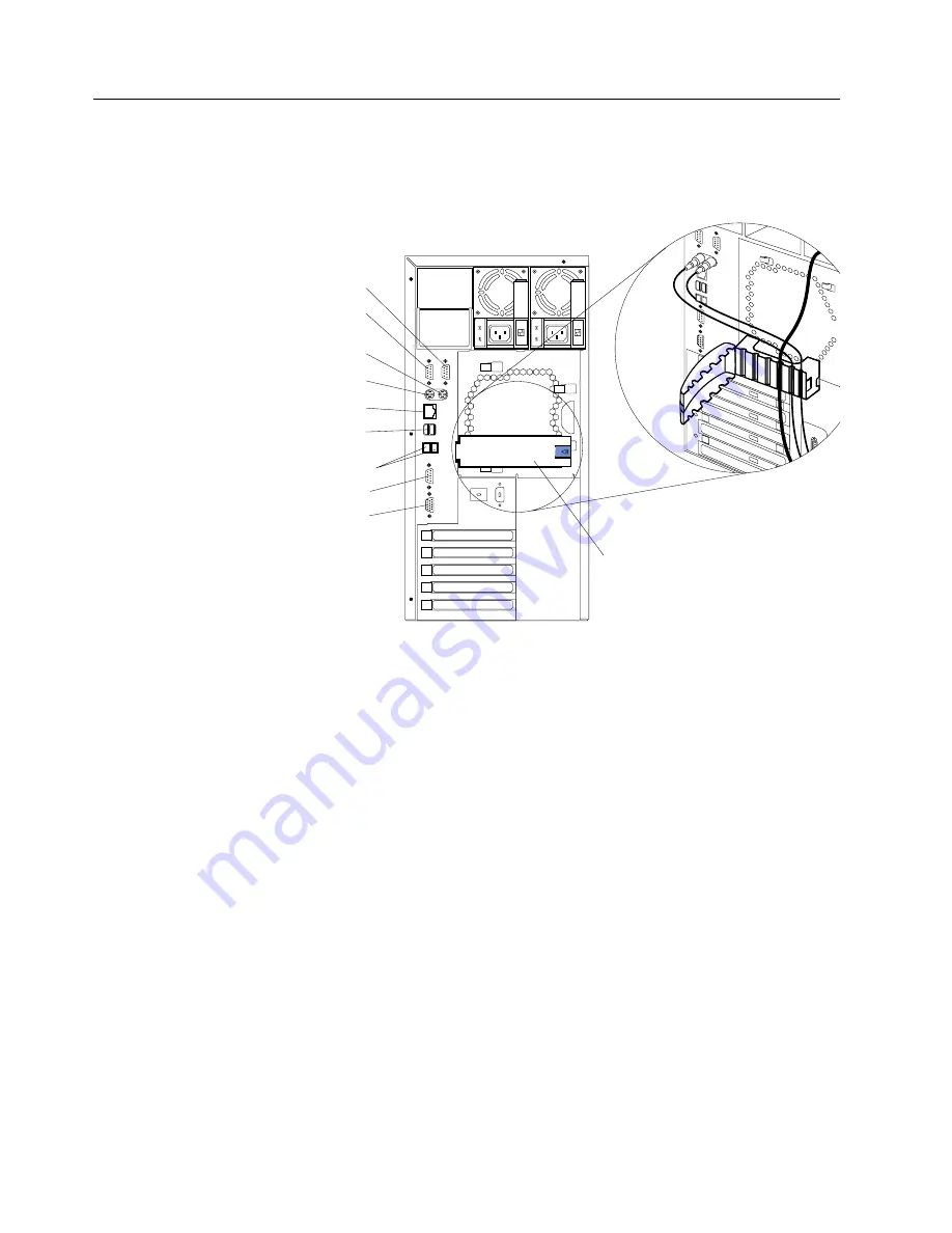
The following illustration shows the input/output connectors and cable routing for the
server.
Note:
The illustrations in this document might differ slightly from your hardware.
Additionally, for rack models, be sure to route the cables through the cable-
management assembly on the rack (see page 20).
Note:
The system management Serial C port and the ISM ports are dedicated for
use by the system management subsystem.
Serial A
Serial B
Serial C
Mouse
Keyboard
Ethernet
Video
Cable-restraint
bracket
ISM-A and B
Universal serial bus
(USB) 1 and 2


