background image


Chapter 5. System board and processor board

. . . . . . . . . . . . . . . .

 99

System-board component locations

. . . . . . . . . . . . . . . . . . . . . . . . .

 99

System-board jumpers

 . . . . . . . . . . . . . . . . . . . . . . . . . . . . . . . .

100

Processor-board component locations

. . . . . . . . . . . . . . . . . . . . . . .

 101

Processor-board jumper and switches

. . . . . . . . . . . . . . . . . . . . . . .

 102

Changing jumper positions

. . . . . . . . . . . . . . . . . . . . . . . . . . . . .

 103

Chapter 6. Solving problems

 . . . . . . . . . . . . . . . . . . . . . . . . . .

107

Diagnostic tools overview

. . . . . . . . . . . . . . . . . . . . . . . . . . . . . .

 107

Diagnostic programs

 . . . . . . . . . . . . . . . . . . . . . . . . . . . . . . . . .

110

Power-on self-test (POST) messages

. . . . . . . . . . . . . . . . . . . . . . .

 112

Power-on self test (POST) beep codes

. . . . . . . . . . . . . . . . . . . . . .

 122

Recovering BIOS

 . . . . . . . . . . . . . . . . . . . . . . . . . . . . . . . . . . .

124

Diagnostic error message tables

. . . . . . . . . . . . . . . . . . . . . . . . . .

 125

Ethernet controller messages

. . . . . . . . . . . . . . . . . . . . . . . . . . . .

 136

Troubleshooting

 . . . . . . . . . . . . . . . . . . . . . . . . . . . . . . . . . . . .

143

Resolving configuration conflicts

. . . . . . . . . . . . . . . . . . . . . . . . . .

 151

Identifying problems using status LEDs

. . . . . . . . . . . . . . . . . . . . . .

 151

Replacing the battery

. . . . . . . . . . . . . . . . . . . . . . . . . . . . . . . .

 157

Chapter 7. Getting help, service, and information

. . . . . . . . . . . . . .

 161

Service support

 . . . . . . . . . . . . . . . . . . . . . . . . . . . . . . . . . . . .

162

Before you call for service

. . . . . . . . . . . . . . . . . . . . . . . . . . . . . .

 163

Getting customer support and service

. . . . . . . . . . . . . . . . . . . . . . .

 163

Purchasing additional services

. . . . . . . . . . . . . . . . . . . . . . . . . . .

 166

Ordering publications

 . . . . . . . . . . . . . . . . . . . . . . . . . . . . . . . .

169

Appendix A. Installing a server in a rack enclosure

. . . . . . . . . . . .

 171

Appendix B. Product warranties and notices

. . . . . . . . . . . . . . . .

 179

Warranty Statements

 . . . . . . . . . . . . . . . . . . . . . . . . . . . . . . . . .

179

Notices

 . . . . . . . . . . . . . . . . . . . . . . . . . . . . . . . . . . . . . . . . .

188

Electronic emission notices

. . . . . . . . . . . . . . . . . . . . . . . . . . . . .

 191

Index

 . . . . . . . . . . . . . . . . . . . . . . . . . . . . . . . . . . . . . . . . . .

193

iv

IBM xSeries User's Reference 


Summary of Contents for eServer 240 xSeries

Page 1: ...User s Reference xSeries 240...

Page 2: ...warranties and notices on page 179 First Edition October 2000 Copyright International Business Machines Corporation 2000 All rights reserved Note to U S Government Users Documentation related to rest...

Page 3: ...tion overview 19 The Configuration Setup Utility program 20 Using the Configuration Setup Utility main menu 21 Configuring options 30 Resolving configuration conflicts 30 Using the SCSISelect utility...

Page 4: ...tic error message tables 125 Ethernet controller messages 136 Troubleshooting 143 Resolving configuration conflicts 151 Identifying problems using status LEDs 151 Replacing the battery 157 Chapter 7 G...

Page 5: ...onsignes de s curit Vor der Installation dieses Produkts die Sicherheitshinweise lesen Prima di installare questo prodotto leggere le Informazioni sulla Sicurezza Lees voordat u dit product installeer...

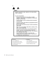
Page 6: ...is evidence of fire water or structural damage Disconnect the attached power cords telecommunications systems networks and modems before you open the device covers unless instructed otherwise in the...

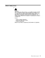
Page 7: ...dule containing a lithium battery replace it only with the same module type made by the same manufacturer The battery contains lithium and can explode if not properly used handled or disposed of Do no...

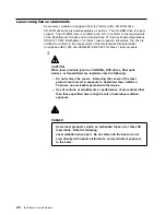
Page 8: ...or Class 1 laser products 3 CAUTION When laser products such as CD ROMs DVD drives fiber optic devices or transmitters are installed note the following Do not remove the covers Removing the covers of...

Page 9: ...nternal drives Instructions for connecting external options are also included in this chapter Chapter 5 System board and processor board contains information about the system board and processor board...

Page 10: ...Attention These notices indicate possible damage to programs devices or data An attention notice is placed just before the instruction or situation in which damage could occur Caution These notices in...

Page 11: ...ver comes with a three year limited warranty and IBM Server Start Up Support You can obtain up to date information about your xSeries 240 server and other IBM server products at http www ibm com eserv...

Page 12: ...tics and Advanced System Management Processor upgrades when available can update EEPROMs on the system board Security Features Door and side cover lock tower model only Power on and administrator pass...

Page 13: ...Sine wave input 50 to 60 Hz is required Input voltage Low range Minimum 90 V ac Maximum 137 V ac High range Minimum 180 V ac Maximum 265 V ac Input kilovolt amperes kVA approximately Minimum configura...

Page 14: ...ers in these slots without turning off the server Redundant cooling and power capabilities The redundant cooling and hot swap capabilities of the fans in your server allow continued operation if one o...

Page 15: ...etwork LAN Redundant network interface card The addition of an optional redundant network interface card NIC provides a failover capability to a redundant Ethernet connection If a problem occurs with...

Page 16: ...system problem determination support Power and temperature monitoring Fault resilient startup Hot swap drive bays Support for hot plug PCI adapters Error codes and messages System error logging Upgrad...

Page 17: ...ontrols and indicators The most commonly used controls and indicators on the front of the server appear in the following illustrations Tower model Rack model Chapter 1 Introducing the IBM xSeries 240...

Page 18: ...s rapidly three flashes per second the controller is identifying the drive 6 Hard Disk Activity Light Each of the hot swap drive bays has a Hard Disk Activity light When this green light is flashing t...

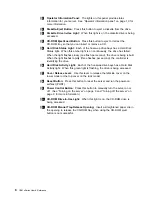
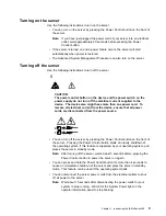
Page 19: ...rom the device ensure that all power cords are disconnected from the power source 1 2 You can turn off the server by pressing the Power Control button on the front of the server Pressing the Power Con...

Page 20: ...en there is microprocessor 1 activity 5 Processor 2 Activity Light This green light is on when there is microprocessor 2 activity 6 Information Light This amber light is on when the information log co...

Page 21: ...aisy chain cable in half duplex mode 2 External Connector Knockout Your server has an external connector knockout that can be used when you install options 3 PCI Expansion Slots Your server has five a...

Page 22: ...lots Your server has two non hot plug PCI expansion slots 9 Parallel Connector A signal cable for a parallel device such as a printer connects here 1 SCSI Connector External SCSI devices attach here F...

Page 23: ...n install a third power supply See Installing a hot swap power supply on page 79 for instructions about installing an additional power supply and information about power redundancy Note See Power cord...

Page 24: ...ovides a power cord with a grounded attachment plug to use with this IBM product To avoid electrical shock always use the power cord and plug with a properly grounded outlet IBM power cords used in th...

Page 25: ...n Sudan Sweden Syria Togo Tunisia Turkey former USSR Vietnam former Yugoslavia Zaire Zimbabwe 13F9997 Denmark 14F0015 Bangladesh Burma Pakistan South Africa Sri Lanka 14F0033 Antigua Bahrain Brunei Ch...

Page 26: ...16 IBM xSeries User s Reference...

Page 27: ...touch on the keyboard and your hands and fingers relaxed You can change the angle of the keyboard for maximum comfort by adjusting the position of the keyboard feet Viewing Distance Lower Back Suppor...

Page 28: ...air escape through vents Blocking the air vents can cause overheating which might result in a malfunction or damage Place the server and monitor so that nothing blocks the air vents usually 15 cm 6 i...

Page 29: ...eral the greater the number and variety of hardware devices and software programs that you install in your server the more you will have to interact with your server and your devices to correctly conf...

Page 30: ...mes with the option before making changes To start the Configuration Setup Utility program 1 Turn on the server and watch the screen 2 When the message Press F1 for Configuration Setup appears press F...

Page 31: ...e setting for the selected menu item then press Enter 3 Repeat step 1 through step 2 for each setting that you want to change Press Esc to return to the Configuration Setup Utility main menu 4 After m...

Page 32: ...data VPD for some server components Devices and I O Ports Software recognizes ports through their port assignments Each port must have a unique port assignment The Configuration Setup Utility program...

Page 33: ...that is sent to the service processor Advanced System Management Processor each time the server is started Use the number keys to enter the hours and minutes and or to add or subtract from the system...

Page 34: ...n password prompt then start the Configuration Setup Utility program and change the power on password Using the power on password menu When a power on password is set you must enter a password each ti...

Page 35: ...word or press Esc to cancel the request and return to the System Security menu To allow the system to start in unattended start mode when a power on password is set 1 Select Power on Password from the...

Page 36: ...nistrator Password from the System Security menu then press Enter The Administrator Password menu appears 2 Select Delete Administrator Password then press Enter 3 A confirmation window appears Press...

Page 37: ...given boot precedence The first drive that is attached to the selected adapter will be assigned drive number 80L and the operating system will start from that drive The default for boot precedence is...

Page 38: ...ced Setup choice Exit the PCI Utility without saving changes to ignore the changes restore the previous settings and return to the Advanced Setup choice Note You can use the menu selections to save se...

Page 39: ...ecent error codes and messages that the system generated during POST You can clear the error log by selecting Clear error logs System Event Error Log Select System Event Error Log to view the system e...

Page 40: ...solve configuration conflicts See Resolving configuration conflicts Resolving configuration conflicts The resources used by your server consist of interrupt requests direct memory access I O port addr...

Page 41: ...sitions on page 103 5 Remove the device or adapter Some configurations are not supported If you must remove an adapter see Working with adapters on page 53 Resolving software configuration conflicts T...

Page 42: ...gram You will be prompted to select either channel A internal or channel B external Use the Up Arrow or Down Arrow key to move the highlight bar to the various menu choices Press Esc to return to the...

Page 43: ...for Fast SCSI devices Advanced Configuration Options Select this choice to view or change the settings for advanced configuration options These options include enabling support for large hard disk dr...

Page 44: ...the Low Level Format program on the hard disk drive As a last resort before replacing a failing hard disk drive Note For information about backing up all of your files see your operating system docum...

Page 45: ...ng system documentation For troubleshooting information see Troubleshooting the Ethernet controller on page 148 If you need additional Ethernet connections you can install an Ethernet adapter such as...

Page 46: ...re currently is supported by OS 2 Windows NT Server and IntraNetWare The setup required for each operating system follows OS 2 Note The OS 2 operating system does not support hot plug operations 1 Add...

Page 47: ...installed If the adapter device driver is installed before the PCI Hot Plug Solution package the adapter device driver will not recognize the hot plug code This happens because the adapter device dri...

Page 48: ...e the IBM Hot Plug PCI for Windows NT Server 4 0 package installed on your server you will not see the Enable for DMI Hot Swap Support check box If the Enable for DMI Hot Swap Support check box is not...

Page 49: ...ccurs A message is generated to the operating system console The custom counters for the device driver contains variables that define the state of the failover function and the location of the redunda...

Page 50: ...40 IBM xSeries User s Reference...

Page 51: ...complete details about installing or removing a hot swap or hot plug component see the information provided in this chapter The blue color on components and labels indicates touch points where a comp...

Page 52: ...ves 2 Unplug all the power cords from electrical outlets 3 Disconnect all communication cables from external receptacles 4 Disconnect all cables and power cords from the back of the server Note Reconn...

Page 53: ...is evidence of fire water or structural damage Disconnect the attached power cords telecommunications systems networks and modems before you open the device covers unless instructed otherwise in the...

Page 54: ...er clips hair pins or screws into the server Handling static sensitive devices Attention Static electricity can damage electronic devices and your system To avoid damage keep static sensitive devices...

Page 55: ...reliability Be sure to leave space around the server to allow the server cooling system to work properly On a tower model leave about 127 mm 5 in of space around the front and rear of the server On a...

Page 56: ...you are Installing or removing a hot plug PCI adapter go to Working with adapters on page 53 Installing or replacing a hot swap hard disk drive go to Installing internal drives on page 67 Installing o...

Page 57: ...nplug all power cords cables from electrical outlets 4 Note the location of the remaining cables and cords then disconnect them from the back of the server If you are Installing or removing a non hot...

Page 58: ...t other than a hot swap hard disk drive hot plug adapter hot swap power supply or hot swap fan turn off the server and all attached devices and disconnect all external cables and power cords see Prepa...

Page 59: ...nal cables and power cords see Preparing to install options on page 46 2 Release the left and right side latches 2 and pull the server out of the rack enclosure until both slide rails lock Note When t...

Page 60: ...U S NON RED UNDAN T PO W ER SU PP LY 1 2 3 A B 1 2 3 FA N TE MPE RAT URE 2 1 1 Flange 2 Server door To remove the server door 1 Unlock and open the server door 2 2 Locate the flange 1 on the top edge...

Page 61: ...zel 1 Move the blue bezel release lever 1 following the curve of the lever opening 2 Lift the bezel tabs out of the slots 3 and pull the bezel 2 away from the server front Store the bezel in a safe pl...

Page 62: ...To remove the trim bezel 1 Move the blue bezel release lever 1 following the curve of the lever opening 2 Lift the bezel tabs out of the slots 3 and pull the bezel 2 away from the server front Store...

Page 63: ...ntroller This video controller is an integrated component on the system board It is not in an expansion slot The integrated video controller has super video graphics array SVGA technology The integrat...

Page 64: ...have the same meaning they are duplicated to be visible from outside or inside the server An Attention LED flashes approximately once per second when it is on The meaning of the Attention LEDs is def...

Page 65: ...n changed PCI slots 1 and 2 system board SCSI devices and then PCI slots 3 through 5 See Start Options on page 27 for information about changing the boot precedence Note The performance of the PCI ada...

Page 66: ...ating system and adapter also support the hot add feature you can install a new adapter without turning off the power to the server Note You do not need to turn off the server to install or remove a h...

Page 67: ...Refer to the following illustrations of the rack model while you perform the steps in this procedure Chapter 4 Installing options 57...

Page 68: ...on page 48 or Removing the cover rack model on page 49 2 Determine which PCI adapter expansion slot you will use for the adapter Note You can use only PCI slots 3 5 hot plug PCI adapters 3 Disable the...

Page 69: ...ter 8 by its top edge or upper corners and align it with the expansion slot on the system board b Press the adapter firmly into the expansion slot Attention When you install an adapter in the server b...

Page 70: ...ver from the server Store it in a safe place for future use Attention Expansion slot covers must be installed on all vacant slots This maintains the electromagnetic emissions characteristics of the sy...

Page 71: ...ice label on the inside of the cover of your server shows cable routing for an optional RAID adapter 2 Connect the end of the SCSI cable that you disconnected from the SCSI cable extender to the RAID...

Page 72: ...rver operation when you install a new or an additional microprocessor use microprocessors that have the same cache size and type and the same clock speed Microprocessor internal and external clock fre...

Page 73: ...he steps in this section 4 5 6 1 Terminator card 2 Microprocessor connector 2 U6 3 Voltage regulator module VRM connector for second VRM 4 VRM for first microprocessor VRM 1 5 Microprocessor connector...

Page 74: ...any unpainted metal surface on the server then remove the microprocessor from the package b Center the microprocessor 8 over the microprocessor connector 2 and carefully press the microprocessor into...

Page 75: ...tor 2 If you install four DIMMs you must install the fourth one in DIMM connector 3 Note The size of the DIMMs in the other memory connectors DIMM connectors 1 2 and 3 does not matter Refer to the fol...

Page 76: ...l the DIMM a Turn the DIMM 1 so that the pins align correctly with the connector 5 b Insert the DIMM into the connector by pressing on one edge of the DIMM and then on the other edge of the DIMM Be su...

Page 77: ...do so now otherwise go to Completing the installation on page 85 Installing internal drives Different types of drives allow your system to read multiple types of media and store more data Several type...

Page 78: ...nd cooling of the server are both protected by having bays A and B covered or occupied When you install a drive save the filler panel from the bay in case you later remove the drive and do not replace...

Page 79: ...o the SCSI HDD backplane 2 Connect the end of the SCSI cable that you disconnected from the SCSI cable extender to the RAID adapter The other end of the cable is connected to the SCSI HDD backplane th...

Page 80: ...in your server verify that you have all the cables and any other equipment specified in the documentation that comes with the internal drive You might also need to perform certain preinstallation act...

Page 81: ...e The EMI integrity and cooling of the server are both protected by having the non hot swap bays covered or occupied When you install a drive save the filler panel from the bay in case you later remov...

Page 82: ...ve If you are installing a digital linear tape DLT backup drive 1 the slide rails 4 and screws are included in the box with your server documentation 7 Place the drive so that the slide rails engage i...

Page 83: ...all hot swap drives in these bays However you must turn off the server when performing any steps that involve installing or removing cables Before you begin Read Electrical safety on page 42 and Handl...

Page 84: ...se with half high drives 2 Filler panel slim high HDD NMI SM I SE RV IC E PR OCES SO R BU S NON RED UNDA NT TE MPE RAT URE 3 Drive 4 Screws 5 Drive tray 6 Drive tray handle in open position 74 IBM xSe...

Page 85: ...ard disk drive 3 in the hot swap bay a Ensure the tray handle 6 is open that is perpendicular to the drive b Align the drive tray assembly so that it engages the guide rails in the bay c Gently push t...

Page 86: ...e data This situation is especially relevant if your server has a RAID adapter installed and you assigned RAID level 1 or 5 to the logical drives in your disk array The RAID adapter can rebuild the da...

Page 87: ...of the tower model while you perform the steps in this procedure HDD NMI SM I SE RV IC E PR OCES SO R BU S NON RED UNDA NT TE MPE RAT URE 3 Drive 4 Screws 5 Drive tray 6 Drive tray handle in open posi...

Page 88: ...Place the new hard disk drive on the hot swap tray and being careful not to over tighten the screws attach the drive to the tray using four screws 5 Install the hard disk drive in the hot swap bay a E...

Page 89: ...ng properly See Power supplies on page 13 for details 8 CAUTION Never remove the cover on a power supply or any part that has the following label attached Hazardous voltage current and energy levels a...

Page 90: ...procedure Note You do not need to turn off the power to the server to install hot swap power supplies 1 Power supply 2 Filler panel 3 Cable restraint bracket 4 Power cord connector 5 Handle on power...

Page 91: ...AC Power light 6 on the power supply are lit indicating that the power supply is operating correctly 7 If you have other options to install or remove do so now otherwise go to Completing the installa...

Page 92: ...bay 3 If you are not replacing the power supply a Install a power supply filler panel 2 Note During normal operation each power supply bay must have either a power supply or filler panel installed fo...

Page 93: ...rations show the replacement of a hot swap fan assembly Refer to these illustrations while performing the steps in this procedure CPU VRM MEMORY HDD PCI BUS NMI SMI SERVICE PROCESSOR BUS NON REDUNDANT...

Page 94: ...ee Diagnostic LED panel on page 153 and the LEDs located on the fan assemblies 3 Remove the fan assembly from the server by pressing the orange release latch 3 6 or 8 for the fan and pulling the fan a...

Page 95: ...e installation for the tower model 1 Install the left side cover if it was removed CP U VR M ME MO RY HD D PC I BU S NM I SM I SE RV IC E PR OC ES SO R BU S NO N RE DU ND AN T PO WE R SU PP LY 1 2 3 A...

Page 96: ...E DU ND AN T PO W ER SU PP LY 1 2 3 A B 1 2 3 FA N TE MPE RA TU RE 1 Trim bezel 2 Slots hidden by bezel a Place the tabs at the bottom edge of the trim bezel 1 in the slots 2 at the bottom front of th...

Page 97: ...ance of at least 127mm 5inches on the front and rear of the server to allow for air circulation 5 If you disconnected any cables from the back of the server reconnect the cables then plug the power co...

Page 98: ...Flanges a Align the top cover 1 with the top of the server about 25mm 1inch from the front of the server the flanges on the left and right sides of the cover should be on the outside of the server cha...

Page 99: ...isconnected any cables from the back of the server reconnect the cables then plug the power cords into properly grounded electrical outlets Note If necessary see Input output connectors and expansion...

Page 100: ...SCSI devices You can attach a SCSI storage expansion enclosure to your server Cabling requirements The SCSI controller in your server has one channel that can be used to attach external devices This...

Page 101: ...nal devices such as printers keyboards and displays to your server The I O connectors on your server include Two serial port connectors One management port C connector One parallel port connector One...

Page 102: ...signments of this connector conform to the industry standard 1 5 6 9 The following table shows the pin number assignments for the serial port connectors When you turn on your server the POST routine a...

Page 103: ...tine assigns the parallel port a specific port address You can change the parallel port assignment by using the Configuration Setup Utility program See Devices and I O Ports on page 22 Table 5 Paralle...

Page 104: ...or monochrome 3 Blue 4 Monitor ID bit 2 5 Ground 6 Ground 7 Ground 8 Ground 9 5 V dc 10 Ground 11 Monitor ID bit 0 12 DDC SDA 13 Horizontal synchronization Hsync 14 Vertical synchronization Vsync 15...

Page 105: ...nnectors and expansion slots on page 11 for the location of the connector 6 4 2 1 3 5 The following table shows the pin number assignments for the connector used by the auxiliary device port Table 8 A...

Page 106: ...ectors Table 9 68 pin SCSI port connector pin number assignments Pin Signal Pin Signal 1 Data 12 35 Data 12 2 Data 13 36 Data 13 3 Data 14 37 Data 14 4 Data 15 38 Data 15 5 Data P1 39 Data P1 6 Data 0...

Page 107: ...t the cabling in the network be Category 5 or higher See Configuring the Ethernet controller on page 35 for additional information about the Ethernet controller Table 10 shows the pin number assignmen...

Page 108: ...the connector Each USB device is accessed by a unique USB address A device called a hub is used to convert the USB port into multiple attachment points A hub has multiple ports where peripherals can b...

Page 109: ...n your server 1 Dual serial and PCI hot plug control switch connector J1 2 Microprocessor board connector J4 J8 3 Operator information panel connector J29 4 Reserved J32 5 Reserved J10 6 Diskette driv...

Page 110: ...ond to the highlighted numbers on the illustration in System board component locations on page 99 Note Turn off the server and disconnect the power cords before moving any jumpers The following illust...

Page 111: ...pply connector J12 12 Power supply connector J14 13 VRM 2 connector J13 14 VRM 2 Error LED CR19 15 VRM 1 Error LED CR17 16 VRM 1 connector J5 17 Fans 1 and 2 connector J8 18 Switch block 2 SW2 19 Swit...

Page 112: ...t and component damage might occur Be sure that the microprocessor core frequency selection is properly set Table 13 Processor board jumpers Jumper name Description 6 J15 Reserved The default position...

Page 113: ...ram and change the power on password See Using the power on password menu on page 24 Change switch 4 of switch block 2 SW2 to the ON position to bypass the power on password check You can then start t...

Page 114: ...sconnect the server power cords 2 Remove the server cover see Preparing to install options on page 46 3 Do one of the following Lift the jumper straight off the pin block Align the holes in the bottom...

Page 115: ...position for a three pin jumper block 1 Turn off the server then disconnect the server power cords 2 Remove the server cover see Preparing to install options on page 46 3 Lift the jumper straight off...

Page 116: ...106 IBM xSeries User s Reference...

Page 117: ...he system board These programs are the primary method of testing the major components of your server such as the the system board Ethernet controller video controller RAM keyboard mouse pointing devic...

Page 118: ...e troubleshooting information provided with your server to determine the cause of the problem and the action to take Flash the latest levels of BIOS service processor diagnostics and RAID code You can...

Page 119: ...st screen of your operating system or application program appears and the System POST Complete OK light is illuminated on the operator information panel If POST detects a problem more than one beep so...

Page 120: ...The system error log contains all error and warning messages issued during POST and all system status messages from the Advanced System Management Processor See System Event Error Log on page 29 for i...

Page 121: ...the server stops during testing and you cannot continue restart the server and try running the diagnostic programs again If the problem persists have the system serviced 3 If the diagnostic tests do n...

Page 122: ...d in memory while the server is turned on Turning off the power clears the test log To view the Test Log 1 Turn on the server and watch the screen If the server is turned on already shut down your ope...

Page 123: ...you just installed a microprocessor verify that the microprocessor is installed and seated correctly 2 If the problem persists check to see if the system has isolated the problem to a microprocessor I...

Page 124: ...formation about using the Configuration Setup Utility program see Using the Configuration Setup Utility main menu on page 21 If the message appears again shutdown the server reseat the memory modules...

Page 125: ...ks up that is the logon data fields are no longer available to the user 201 An error occurred during the memory controller test This error can be caused by Incorrectly installed memory A failing memor...

Page 126: ...correctly Start the Configuration Setup Utility program see Chapter 3 Configuring your server In the Advanced Setup menu select Memory Settings and enable the DIMM See Advanced Setup on page 27 2 If...

Page 127: ...le or the device is probably failing See the documentation that comes with the serial device for additional testing information If the POST error message reappears have the system serviced 1162 The se...

Page 128: ...on page 53 For information about setting interrupts see PCI Slot Device Information on page 28 1962 No valid startup devices were found The system cannot find the startup drive or operating system Ac...

Page 129: ...stic tests do not find a problem and the POST error message remains have the system serviced 00012000 Processor machine check Action 1 Update the system BIOS Refer to Chapter 7 Getting help service an...

Page 130: ...r adapters are set correctly in the Configuration Setup Utility program If the memory resource settings are not correct change the settings For information about using the Configuration Setup Utility...

Page 131: ...tem BIOS to a level that supports the microprocessors installed in the server Refer to Chapter 7 Getting help service and information on page 161 for information about obtaining updates 01298102 The u...

Page 132: ...sor has failed replace the startup microprocessor Note If the server has only one microprocessor installed that microprocessor is installed in microprocessor connector U5 and is the startup boot micro...

Page 133: ...integrated video adapter on the system board is being used If an optional video adapter is being used replace the failing video adapter One long and two short beeps This beep combination indicates tha...

Page 134: ...ual has failed Action Have the system serviced 1 2 4 1 3 1 1 3 2 3 3 1 3 3 3 RAM refresh verification has failed First 64 Kb RAM test has failed First 64 Kb RAM parity test has failed A memory size mi...

Page 135: ...from diskette xx is displayed When programming is underway a further progress report Programming block n of 7 yy is displayed When recovery is complete Recovery complete remove the diskette and retur...

Page 136: ...the text message follows Text messages The text message format is Function Name Result Test specific string where Function Name is the name of the function being tested when the error occurred This co...

Page 137: ...IOS Advanced System Management Processor and diagnostics microcode installed If the problem persists have the system serviced Failed Built in serial port on system board Action Have the system service...

Page 138: ...ed System Management Processor and diagnostics microcode installed If the problem persists have the system serviced Failed SCSI adapter in slot n failed register counter power test where n is the slot...

Page 139: ...AID adapter in slot n If the problem persists have the system serviced Failed Logical drive on system board adapter Action Run the ServeRAID Configuration Utility program If the problem persists have...

Page 140: ...ce the indicated microprocessor and run the microprocessor diagnostic program again If the problem persists have the system serviced Failed Microprocessor in socket id xyz where xyz identifies the mic...

Page 141: ...stall a VRM If the problem persists have the system serviced Function Advanced System Management Processor messages 165 Result Test specific string Note If you receive any diagnostic error messages th...

Page 142: ...If the problem persists have the system serviced Failed DIMM location Jn where n is the number of the socket containing the failing DIMM Note The DIMM Error LED for the failing DIMM will be on See Pr...

Page 143: ...Refer to Chapter 7 Getting help service and information on page 161 for information about obtaining updates 2 If the problem persists replace the identified microprocessor If the problem persists have...

Page 144: ...he system serviced Failed BIOS drive n where n is the drive bay number Action Have the system serviced Function magnetic tape drive messages 264 Result Test specific string Note If you receive any dia...

Page 145: ...problem persists have the system serviced Failed On system board keyboard test failed Action 1 Replace the keyboard 2 If the problem persists replace the keyboard cable If the problem persists have th...

Page 146: ...Action 1 Change the configuration to enable the modem 2 If the problem persists replace the modem If the problem persists have the system serviced Ethernet controller messages The integrated Ethernet...

Page 147: ...s in the server Then restart the server PCNTNW NW 074 The hardware interrupt cannot be set Explanation An attempt was made to initialize a given hardware interrupt The attempt was not successful Actio...

Page 148: ...ies of this device driver to enter a new address the local bit must be set You entered an address without the local bit set The device driver has set the local bit Action None necessary message is for...

Page 149: ...l Manager Input Output Control IOCTL failed Explanation The NDIS stack is not configured correctly in the PROTOCOL INI file Action Check and correct your configuration PCNTND 11 Protocol Manager regis...

Page 150: ...CNTND 33 PCNET device with specified IOBASE is already in use Explanation The specified I O address number is already in use by another Ethernet controller or device Action Remove the I O address sett...

Page 151: ...t the Ethernet controller is enabled See PCI Slot Device Information on page 28 If the Ethernet controller is enabled go to Diagnostic programs on page 110 to run the diagnostic programs pnt0 12 Devic...

Page 152: ...rver Action Modify your hardware settings Run the NETCONFIG program to search for another Ethernet controller pnt0 22 add_intr_handler failed Out of range IPL Explanation The interrupt request IRQ tha...

Page 153: ...r must be turned on If the server is on and the tray does not eject insert the end of a paper clip into the manual tray release opening If the drive still does not work correctly have the system servi...

Page 154: ...rate available To reset the refresh rate use a utility program such as AnyView Professional or WinMode Wavy unreadable rolling distorted screen or screen jitter If the monitor self tests show the mon...

Page 155: ...problem still exists have the system serviced Microprocessor problems Action The server emits a continuous tone during POST The startup boot microprocessor is not working properly If your server conta...

Page 156: ...on verify that 1 The cables for all external SCSI options are connected correctly 2 The last option in each SCSI chain or the end of the SCSI cable is terminated correctly 3 Any external SCSI option i...

Page 157: ...ble for use by the operating system This port does not appear in the Configuration Setup Utility program menus it can be configured using the systems management software provided with your server If t...

Page 158: ...tware verify that 1 Your server has the minimum memory requirements needed to use the software For memory requirements refer to the information that comes with the software Note If you have just insta...

Page 159: ...and server are using the same protocol Test the Ethernet controller How you test the Ethernet controller depends on which operating system you are using see the Ethernet controller device driver READ...

Page 160: ...oradic Check the following Make sure that you are using Category 5 cabling when operating the server at 100 Mbps Make sure that the cables are not close to noise inducing sources like fluorescent ligh...

Page 161: ...the hardware configuration setup An alternative way to resolve memory address conflicts is to change the address of the conflicting hardware option Identifying problems using status LEDs Your server...

Page 162: ...Power Control button on the front of the server is in the Off position Action Press the Power Control button to start the server 2 The power supply has failed Action Replace the power supply If the p...

Page 163: ...RATURE Light path diagnostics You can use the light path diagnostics built into your server to quickly identify the type of system error that occurred Your server is designed so that any LEDs that are...

Page 164: ...rocessor is installed in the wrong connector 1 Check the Microprocessor Error LEDs on the processor board 2 Turn off the server reseat the microprocessor indicated by the lit Microprocessor Error LED...

Page 165: ...If the error log indicates a problem with the integrated SCSI controller have the system serviced 2 If you cannot correct the problem from the information in the error log try to determine the failin...

Page 166: ...Replace power supply 2 POWER SUPPLY 3 Power supply 3 has failed Replace power supply 3 POWER SUPPLY NON REDUNDANT Power supply redundancy has been lost 1 If one of the power supply LEDs is on replace...

Page 167: ...art Number 33F8354 or an equivalent type battery recommended by the manufacturer If your system has a module containing a lithium battery replace it only with the same module type made by the same man...

Page 168: ...d removing adapters from the hot plug PCI slots 4 Remove the plastic dividers between the hot swap PCI slots to allow access to the battery 5 Remove the battery a Use one finger to lift the battery cl...

Page 169: ...to wait approximately 20 seconds after you plug the power cord of your server into an electrical outlet for the Power Control button to become active 10 Start the Configuration Setup Utility program a...

Page 170: ...160 IBM xSeries User s Reference...

Page 171: ...www ibm com pc us ibmpc IBM Commercial Desktop PCs U S http www ibm com pc us intellistation IBM IntelliStation Workstations U S http www ibm com pc us accessories Options by IBM U S http www ibm com...

Page 172: ...llowing services are available during the warranty period Problem determination Trained personnel are available to assist you with determining if you have a hardware problem and deciding what action i...

Page 173: ...umentation that contains troubleshooting procedures and explanations of error messages The documentation that comes with your computer also contains information about the diagnostic tests you can perf...

Page 174: ...fic Web site from these pages Using electronic support services If you have a modem you can get help from several popular services Online information services provide assistance through question and a...

Page 175: ...n by telephone through the IBM PC HelpCenter Please have the following information ready when you call Machine Type and Model Serial numbers of your computer monitor and other components or your proof...

Page 176: ...Service When you register with the International Warranty Service Office you will receive an International Warranty Service Certificate that is honored virtually worldwide wherever IBM or IBM reseller...

Page 177: ...t line In the U S if you prefer to obtain technical support on a pay as you go basis you can use the 900 number support line The 900 number support line provides support for IBM PC products that are o...

Page 178: ...pgrades in the U S include Carry in service to on site service If your warranty provides carry in repair service you can upgrade to on site repair service either standard or premium The standard upgra...

Page 179: ...e for purchase from IBM For a list of publications available in your country In the U S Canada and Puerto Rico call 1 800 879 2755 In other countries contact your IBM reseller or IBM marketing represe...

Page 180: ...170 IBM xSeries User s Reference...

Page 181: ...s procedure you must install parts on the rack enclosure and the server This process can be divided in two parts Preparing the rack enclosure Installing the server into the rack enclosure 82 kg 180 lb...

Page 182: ...can meet the operating parameters as detailed in Features and specifications on page 2 Turn off the server if it is on Preparing the rack enclosure To attach the mounting hardware to the rack enclosur...

Page 183: ...he cage nuts for the slide rail The two holes in the front bracket line up with the cage nuts c Do the same for the other slide rail 1 Left slide rail 2 Left rear 3 Left front d From the outside of th...

Page 184: ...ure the mounting bracket to the rack 1 Right rear 2 Left rear 3 Right front 4 Left front 5 Hitch pin c Attach the free end of the cable management arm to the rear of the left slide rail using a hitch...

Page 185: ...the slide rails lock b Rest the wheel shaped knobs 1 on the slide rails at a point close to the rack c Lower the front of the server until the bottom notch in each chassis bracket fits into the top n...

Page 186: ...server from the rack at a later time 3 Press the safety latches on the slide rails 1 and slide the server about halfway into the rack enclosure Note When the server is fully extended safety latches on...

Page 187: ...taching the cables to the arm with the hook and loop fastener strips provided The wraps are provided for additional cable management 5 Secure the server in the rack enclosure a Slide the server into t...

Page 188: ...ck e Slide the server into the rack enclosure again until the side latches on the front chassis brackets click into place 6 Optional For additional security such as when transporting the rack fasten t...

Page 189: ...wise the following warranties apply only in the country where you acquire the Machine Nothing in this Statement of Warranty affects any statutory rights of consumers that cannot be waived or limited b...

Page 190: ...r reseller will inform you of the available types of service for a Machine based on its country of installation IBM may repair the failing Machine or exchange it at its discretion When warranty servic...

Page 191: ...LOST PROFITS OR SAVINGS EVEN IF IBM ITS SUPPLIERS OR YOUR RESELLER IS INFORMED OF THEIR POSSIBILITY SOME JURISDICTIONS DO NOT ALLOW THE EXCLUSION OR LIMITATION OF INCIDENTAL OR CONSEQUENTIAL DAMAGES...

Page 192: ...ovided for a Machine under warranty such as assistance via telephone with how to questions and those regarding Machine set up and installation will be provided WITHOUT WARRANTIES OF ANY KIND Warranty...

Page 193: ...lies to IBM s suppliers and your reseller It is the maximum for which IBM its suppliers and your reseller are collectively responsible UNDER NO CIRCUMSTANCES IS IBM LIABLE FOR ANY OF THE FOLLOWING 1 T...

Page 194: ...in warranty service for that Machine in any of those countries from either 1 an IBM reseller approved to perform warranty service or 2 from IBM If you purchased an IBM Personal Computer Machine in Alb...

Page 195: ...claim Applicability of suppliers and resellers unchanged The following paragraph is added at the end of this Section IBM s entire liability and your sole remedy whether in contract or in tort in resp...

Page 196: ...warranty relates to right to sell quiet possession or clear title or the goods are of a kind ordinarily acquired for personal domestic or household use or consumption then none of the limitations in t...

Page 197: ...om IBM IBM is liable for no more than items 1 and 2 unchanged GERMANY The IBM Warranty for Machines The following replaces the first sentence of the first paragraph of this Section The warranty for an...

Page 198: ...ted to the charge paid by you for the individual Machine that is the subject of your claim from IBM TURKIYE Production Status The following replaces this Section IBM fulfils customer orders for IBM Ma...

Page 199: ...RANTIES OF MERCHANTABILITY OR FITNESS FOR A PARTICULAR PURPOSE Some jurisdictions do not allow disclaimer of express or implied warranties in certain transactions therefore this statement may not appl...

Page 200: ...g is a Year 2000 Readiness Disclosure Trademarks The following terms are trademarks of the IBM Corporation in the United States or other countries or both Lotus and Domino are trademarks or registered...

Page 201: ...he FCC Rules These limits are designed to provide reasonable protection against harmful interference when the equipment is operated in a commercial environment This equipment generates uses and can ra...

Page 202: ...ce to Customers This apparatus is approved under approval number NS G 1234 J 100003 for indirect connection to public telecommunication systems in the United Kingdom European community directive confo...

Page 203: ...56 non hot plug 60 external options 90 91 adding continued hot swap fan assembly 83 internal drive 67 68 memory 65 power supply 79 address COM port 92 parallel port 93 registering your server 1 serve...

Page 204: ...passing power on password 24 103 C cables 2 drop SCSI 69 category 5 35 97 148 connecting before installing adapter 59 60 safety requirements vi to a non hot swap drive 72 to an adapter 59 61 connector...

Page 205: ...ent interconnect PCI 28 power on self test POST 19 restoring 21 29 Universal Serial Bus USB 23 configuration continued utility programs 19 Configuration Setup Utility program administrator password 25...

Page 206: ...design considerations 1 device configuration error 114 drivers compatibility with network adapters 61 external 90 mouse problems 145 number supported 90 pointing device problems 145 port assignments 2...

Page 207: ...7 description 109 device configuration 114 diagnostic 110 125 diskette drive diagnostic 206 134 Ethernet 136 Ethernet diagnostic 301 135 Ethernet diagnostic 302 135 Ethernet diagnostic 405 135 event e...

Page 208: ...8 PCI configuring 28 rear view 11 features and specification 2 features server 2 fee services 166 filler panel cooling considerations 45 filler panel continued hot swap drive bay 75 non hot swap drive...

Page 209: ...requirements 68 installing adapters general information 53 hot plug 56 non hot plug 60 installing continued battery 158 cover 85 DIMM 65 door 87 external options 90 91 hard disk drives 71 73 hot swap...

Page 210: ...tivity 10 LEDs light emitting diode continued processor board 101 SCSI Hard Drive Activity 10 SERVICE PROCESSOR BUS 153 156 SMI 153 156 system board 99 System Error 10 154 155 156 157 System POST Comp...

Page 211: ...ement Processor diagnostic 165 131 messages continued battery failure 113 CD ROM diagnostic 215 134 core system diagnostic 001 127 device configuration error 114 diagnostic 125 diskette drive diagnost...

Page 212: ...110 options configuring 30 diskettes 110 external connecting 90 91 installation preparation 46 installing 41 internal adapter 53 DIMM 65 drives 68 options continued internal continued memory module k...

Page 213: ...AC Power light 14 connector 12 14 Control button 8 DC Power light 14 filler panel for power supply bay 14 supplies 14 power cables See power cord Power Control button 8 power cord available list of 1...

Page 214: ...product data 22 programs advanced diagnostic 34 diagnostic 110 low level format 34 protecting data 25 the server 41 publications publications ordering 169 R rack connectors 11 power supplies 13 rack...

Page 215: ...light 10 SCSISelect Utility program low level disk format 34 menu description SCSI Disk Utilities 33 starting 32 SCSISelect Utility program continued using 32 security procedures See also password def...

Page 216: ...ests 107 troubleshooting charts 110 143 USB 147 sound acoustical noise output 3 specification and features 2 specifications server 3 speed Ethernet controller 35 keyboard 27 memory 65 Start Options en...

Page 217: ...148 149 overview 110 turning on the server problems 145 two drop SCSI cable 69 two pin jumper blocks 104 types of media 68 U unattended start mode and power on password 23 and system startup 25 defin...

Page 218: ...nty extensions and upgrades 168 warranty service 165 weight of server 3 work area arranging 17 World Wide Web 41 registering your server 1 server product information 1 World Wide Web home page 161 163...

Page 219: ...IBM Part Number 21P9014 Printed in the United States of America 21P9 14...

Reviews: