72
IBM® xSeries 250: User’s Reference
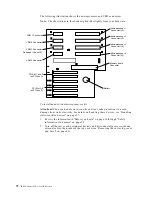
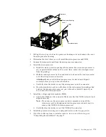
The following illustration shows the microprocessor and VRM connectors.
Note:
The illustrations in this book might differ slightly from your hardware.
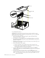
To install an additional microprocessor kit:
Attention:
When you handle static-sensitive devices, take precautions to avoid
damage from static electricity. For details on handling these devices, see “Handling
static-sensitive devices” on page 37.
1.
Review the information in“Before you begin” on page 36 through “Safety
information statements” on page 38.
2.
Turn off the server and peripheral devices, and disconnect all power cords and
external cables; then, remove the top cover (see “Removing the server top cover
and bezel” on page 40).
Microprocessor 2
Connector (J3)
Microprocessor 1
Connector (J2)
Microprocessor 3
Connector (J4)
Microprocessor 4
Connector (J5)
Battery
VRM 1 Connector
VRM 4 Connector
VRM 3 Connector
Reserved (J8 and J9)
VRM 2 Connector
Memory board
Connector
PCI Slot 1 and 2
(on PCI bus A)
PCI Slot 3-6
(on PCI bus B)
Summary of Contents for eServer 250 xSeries
Page 1: ...User s Reference xSeries 250...
Page 2: ......
Page 3: ...IBM IBM xSeries 250 User s Reference SC21 P902 00...
Page 8: ...vi IBM xSeries 250 User s Reference...
Page 14: ...xii IBM xSeries 250 User s Reference...
Page 24: ...10 IBM xSeries 250 User s Reference...
Page 36: ...22 IBM xSeries 250 User s Reference...
Page 108: ...94 IBM xSeries 250 User s Reference...
Page 185: ......
Page 186: ...IBM Part Number 21P9020 Printed in the United States of America 21P9 2...


