background image

 6

IBM  xSeries 342: Installation Guide


Removing the cover and bezel

Removing

 the co

ver and

 bezel

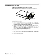
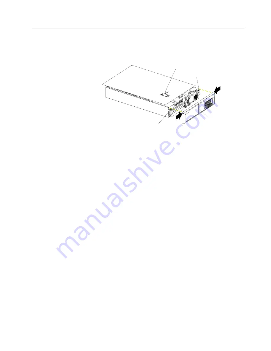
Refer to the following illustration to remove the cover and bezel.

Note: The illustrations in this document might differ slightly from your hardware.

To remove the server top cover:

1.

If you are planning to install or remove any part other than a hot-swap hard disk 
drive, hot-swap power supply, or hot-swap fan, turn off the server and all attached 
devices and disconnect all external cables and power cords.

2.

Lift the cover-release latch. Lift the cover off the server and set the cover aside. 

Attention: For proper cooling and airflow, replace the cover before turning on the 
server. Operating the server for extended periods of time (over 30 minutes) with 
the cover removed might damage server components.

To remove the bezel: 

1.

Press in on the top sides of the bezel, and rotate the bezel away from the server 
front.

2.

Store the bezel in a safe place.

Cover-release latch

Side latch

Side latch

Bezel

Summary of Contents for eServer 342 xSeries

Page 1: ...he server and options Start the server Install options Drives Microprocessors Adapters Memory Did the server start correctly Yes No Use ServerGuide to setup and configure hardware Did configuration complete Use ServerGuide to install operating system Use ServerGuide to install applications such as IBM systems management software and IBM ServeRAID programs System is ready to use Go to the Server Su...

Page 2: ...ting information provided with your server to determine the cause of the problem and the action to take Flash the latest levels of BIOS service processor diagnostics and RAID code You can download this code at http www ibm com pc support No No Yes Yes Yes Check all cables for loose connections and verify that all optional devices you installed are on the ServerProven list You can view the ServerPr...

Page 3: ...IBM IBM xSeries 342 Installation Guide ...

Page 4: ...information in Appendix A Product warranties and notices on page 41 First Edition June 2001 Copyright International Business Machines Corporation 2001 All rights reserved US Government Users Restricted Rights Use duplication or disclosure restricted by GSA ADP Schedule Contract with IBM Corp ...

Page 5: ...rator information panel 24 Chapter 4 Configuring your server 27 Starting the utility programs 27 Using the Configuration Setup Utility program 27 Using the SCSISelect utility program some models 28 Using the PXE boot agent utility program 28 Using the ServerGuide CDs 29 Using the System Updates and Applications CD 30 Chapter 5 Solving Problems 31 Diagnostic tools overview 31 POST beep code descrip...

Page 6: ...ited Kingdom telecommunications safety requirement 52 European Union EMC Directive conformance statement 52 Taiwan electrical emission statement 52 Japanese Voluntary Control Council for Interference VCCI statement 52 Power cords 53 Index 55 ...

Page 7: ...uin asennat tämän tuotteen lue turvaohjeet kohdasta Safety Information Avant d installer ce produit lisez les consignes de sécurité Vor der Installation dieses Produkts die Sicherheitshinweise lesen Prima di installare questo prodotto leggere le Informazioni sulla Sicurezza Les sikkerhetsinformasjonen Safety Information før du installerer dette produktet Antes de instalar este produto leia as Info...

Page 8: ...vi IBM xSeries 342 Installation Guide Antes de instalar este producto lea la información de seguridad Läs säkerhetsinformationen innan du installerar den här produkten ...

Page 9: ...ny equipment when there is evidence of fire water or structural damage Disconnect the attached power cords telecommunications systems networks and modems before you open the device covers unless instructed otherwise in the installation and configuration procedures Connect and disconnect cables as described in the following table when installing moving or opening covers on this product or attached ...

Page 10: ...ent 3 CAUTION When laser products such as CD ROMs DVD drives fiber optic devices or transmitters are installed note the following Do not remove the covers Removing the covers of the laser product could result in exposure to hazardous laser radiation There are no serviceable parts inside the device Use of controls or adjustments or performance of procedures other than those specified herein might r...

Page 11: ...TION The power control button on the device and the power switch on the power supply do not turn off the electrical current supplied to the device The device also might have more than one power cord To remove all electrical current from the device ensure that all power cords are disconnected from the power source 1 2 ...

Page 12: ...upply or any part that has the following label attached Hazardous voltage current and energy levels are present inside any component that has this label attached There are no serviceable parts inside these components If you suspect a problem with one of these parts contact a service technician ...

Page 13: ...ies Documentation CD that provides detailed information about your server Your server comes with a three year limited warranty and 90 Day IBM Start Up Support If you have access to the World Wide Web you can obtain up to date information about your server model and other IBM server products at the following World Wide Web address http www ibm com eserver xseries Record your product information in ...

Page 14: ...iguration Integrated functions Dual channel Ultra160 SCSI controller One 10BASE T 100BASE TX 100BASE FX Intel Ethernet controller with Alert on LAN and Wake on LAN support Two serial ports Two Universal Serial Bus ports Keyboard port Mouse port Video port Integrated System Management ISM Processor Two ISM RJ 45 connectors One system management Serial C port Acoustical noise emissions Sound power i...

Page 15: ...just before the descrip tion of a potentially lethal or extremely hazardous procedure step or situation Handling static sensitive devices Attention Static electricity can damage electronic devices and your system To avoid damage keep static sensitive devices in their static protective packages until you are ready to install them To reduce the possibility of electrostatic discharge observe the foll...

Page 16: ...information about installing or removing a hot swap component see the detailed information in this chapter The blue color on components and labels indicates touch points where a component can be gripped a latch moved and so on Note The illustrations in this document might differ slightly from your hardware Hot swap fan Air baffle Microprocessor Memory module Fan sink Terminator card System board F...

Page 17: ... removed Follow these guidelines when you work inside a server that is turned on Avoid loose fitting clothing on your forearms Button long sleeved shirts before working inside the server do not wear cuff links while you are working inside the server Do not allow your necktie or scarf to hang inside the server Remove jewelry such as bracelets rings necklaces and loose fitting wrist watches Remove i...

Page 18: ... swap fan turn off the server and all attached devices and disconnect all external cables and power cords 2 Lift the cover release latch Lift the cover off the server and set the cover aside Attention For proper cooling and airflow replace the cover before turning on the server Operating the server for extended periods of time over 30 minutes with the cover removed might damage server components T...

Page 19: ... comes with the adapter and follow those instruc tions in addition to the instructions given in this chapter If you need to change the switch or jumper settings on your adapter follow the instructions that come with the adapter You can install full length and half length adapters in all slots Some full length adapters with daughterboards can interfere with SCSI channel B and should not be installe...

Page 20: ...I bus C Note PCI bus A is often referred to as bus 0 PCI bus B is often referred to as bus 1 and PCI bus C is often referred to as bus 2 The system scans PCI slot 1 the system board Ethernet PCI slots 2 5 the system board SCSI and then SCSI channels A and B if you have not changed the boot precedence from the default You can use the Configuration Setup Utility program to change the boot precedence...

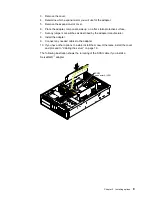
Page 21: ...rotective surface 7 Set any jumpers or switches as described by the adapter manufacturer 8 Install the adapter 9 Connect any needed cables to the adapter 10 If you have other options to install install them now Otherwise install the cover and proceed to Cabling the server on page 19 The following illustration shows the rerouting of the SCSI cable if you install a ServeRAID adapter SCSI connector A...

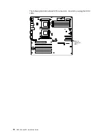
Page 22: ...10 IBM xSeries 342 Installation Guide The following illustration shows SCSI connector A into which you plug the SCSI cable SCSI A connector J24 ...

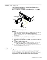
Page 23: ...he tray handle is open 3 Gently push the drive tray assembly into the bay until the drive touches the back plane 4 Push the tray handle down until it locks Note If your server has a RAID adapter installed refer to the information pro vided with the RAID adapter for information about adding a drive 5 If you have other options to install install them now Otherwise install the cover and proceed to Ca...

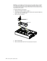
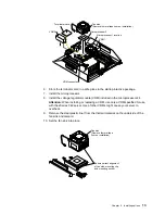
Page 24: ...me clock speed Microprocessor internal and external clock frequencies must be identical To install an additional microprocessor 1 Review the information in Safety on page v 2 Turn off the server and peripheral devices and disconnect all external cables and power cords then remove the cover 3 Remove the fan 3 assembly 4 Remove the air baffle 5 Remove the terminator card from the microprocessor conn...

Page 25: ...ed for use with the xSeries 342 server Use of other VRMs might cause your server to overheat 9 Remove the clear plastic liner from the thermal material on the underside of the fan sink and discard 10 Set the fan sink into place Microprocessor 2 Fan sink Remove thermal tape liner on installation Microprocessor 1 location VRM 1 Terminator card VRM 2 VRM connector Fan sink Remove thermal tape liner o...

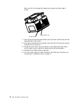
Page 26: ...e spring retention clip on the front of the fan sink the side facing the front of the server 13 Plug the fan sink into the fan sink connector on the system board J46 Make sure the cable is not in a position to interfere with the fan sink operation 14 Reinstall the air baffle and the fan assembly 15 If you have other options to install install them now Otherwise install the cover and proceed to Cab...

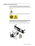
Page 27: ...upply bay locations Note The illustrations in this document might differ slightly from your hardware Statement 8 CAUTION Never remove the cover on a power supply or any part that has the following label attached Hazardous voltage current and energy levels are present inside any component that has this label attached There are no serviceable parts inside these components If you suspect a problem wi...

Page 28: ...dard dual inline memory module DIMM Your server uses a two way interleaved memory configuration You must install matched pairs of memory kits but the set in slots 1 and 4 do not need to be the same size as the set in slots 2 and 3 Notes 1 Your server comes with two dual inline memory modules DIMMs installed in DIMM slots 1 and 4 Install additional DIMMs as a matched pair in DIMM slots 2 and 3 and ...

Page 29: ...afety on page v 2 Turn off the server and peripheral devices and disconnect all external cables and power cords 3 Remove the cover 4 Install the DIMM a Carefully rotate the retaining clips away from the connector and into the open position DIMM 2 DIMM 1 DIMM connector 4 J4 DIMM connector 3 J3 DIMM connector 2 J2 DIMM connector 1 J1 DIMM 2 DIMM 3 DIMM 4 DIMM 1 ...

Page 30: ...ing clips are in the closed position If a gap exists between the DIMM and the retaining clips the DIMM has not been properly installed In this case open the retaining clips and remove the DIMM then reinsert the DIMM e Repeat steps 4a through 4d for the second DIMM then continue with step 5 5 Make sure the retaining clips are in the closed position 6 If you have other options to install install the...

Page 31: ...trations in this section to cable the server and route the cables through the cable management arm The following illustration shows external connectors and cable routing for the server Note The illustrations in this document might differ slightly from your hardware Mouse Serial B Serial C Serial A Keyboard Ethernet Universal Serial Bus USB 1 and 2 Video ISM A ISM B ...

Page 32: ...20 IBM xSeries 342 Installation Guide ...

Page 33: ...button on the front of the server If the server is turned on a power failure occurs and unattended start mode is enabled in the Configuration Setup utility program the server will start automatically when power is restored If ac power is present the server is off and the wake up feature is enabled in the Configuration Setup utility program the wake up feature will turn on the server at the set tim...

Page 34: ...s functioning You can disconnect the server power cords from the electrical outlets to shut off all power to the server Note After disconnecting the power cords wait approximately 15 seconds for your system to stop running Watch for the power on light to stop blinking If the system was turned on by the wake up feature or Wake on LAN feature you can turn it off by either a software runtime or by th...

Page 35: ...our server Power control button Press this button to manually turn the server on or off Reset button Press this button to reset the server and run the power on self test POST You might need to use a pen or the end of a straightened paper clip to press this button Operator information panel The lights on this panel give status information for your server See Operator information panel on page 24 fo...

Page 36: ...ormation panel on the front of the server See Controls and indicators on page 23 for the location of the operator information panel Note The illustrations in this document might differ slightly from your hardware SCSI hard disk drive activity light This green light is on when there is activity on a hard disk drive Ethernet transmit receive activity light When this green light is on there is transm...

Page 37: ... operation when the system is powered off the LED remains green Information light This amber light is on when the information log contains information about certain conditions in your server that might affect performance System error light This amber light is lit when a system error occurs An LED on the diagnostic LED panel will also be on to further isolate the error ...

Page 38: ...26 IBM xSeries 342 Installation Guide ...

Page 39: ...more information on the PXE Boot Agent Utility ServerGuide CDs The ServerGuide CDs include software setup and installation tools specifically designed for IBM xSeries servers You can use these CDs during the initial installation of your server to configure the server hardware and simplify your network operating system installation The ServerGuide CDs also contain a collection of application progra...

Page 40: ...to start the SCSISelect Utility program 1 Turn on the server 2 When the Press CTRL A for SCSISelect Utility prompt appears press Ctrl A 3 When the Would you like to configure the host adapter or run the SCSI disk utility question appears make your selection and press Enter 4 Use the arrow keys to select a choice from the menu Press Esc to exit the SCSISelect Utility program Press the F5 key to swi...

Page 41: ...m pc coupon The ServerGuide software has these features to make setup easier An easy to use interface with online help Diskette free setup and configuration programs that are based on detected hardware Performance Optimizer program which easily tunes your server for your environment A system BIOS update program which updates the BIOS directly from the CD Device drivers that are provided for your s...

Page 42: ...m Updates and Applications CD Be sure to take advantage of the additional software that is provided on the System Updates and Applications CD Note See the CD label for a current list of updates and applications to start the CD and view the online overview ...

Page 43: ...hooting charts These charts list problem symptoms along with suggested steps to correct the problems See the Troubleshooting chart on page 35 for more information Error logs The POST error log contains the three most recent error codes and messages that the system generated during POST The System Event Error Log contains all error messages issued during POST and all system status messages from the...

Page 44: ...st restart the server three times to force the system BIOS code to reset the memory connector or bank of connectors from Disabled to Enabled Repeating short The system board might contain a failing component 1 Verify that the keyboard and pointing devices are connected properly 2 Ensure that nothing is resting on the keyboard 3 Disconnect the pointing device then restart the server If the problem ...

Page 45: ...is fully seated and installed properly 229 L2 cache of a microprocessor Check the installation of your microprocessors 289 Failing DIMM was disabled Verify that your memory is correct for your server and that it is installed properly 301 303 Keyboard and keyboard controller Ensure that the keyboard cable is connected and nothing is resting on the keyboard keys 11xx Serial port error Verify that th...

Page 46: ...hat there are no duplicate SCSI IDs or IRQ assignments Ensure that the hard disk drive is connected properly The Operating System Installation program continuously loops Free up more space on the hard disk drive ServerGuide will not start your NOS CD Ensure that the NOS CD you have is supported by ServerGuide See the Setup and Installation CD label for a list of NOS versions supported Cannot insta...

Page 47: ...arts 2 If you cannot find the problem in the troubleshooting charts run the diagnostic programs If you have run the diagnostic test programs or if running the tests does not reveal the problem call for service Device Suggested action CD ROM drive Verify that 1 The primary IDE channel is enabled in the Configuration Setup Utility program 2 All cables and jumpers are installed correctly 3 The correc...

Page 48: ...d correctly 2 Try using another mouse or pointing device If the problem remains call for service Memory problems Verify that 1 The memory modules are seated properly 2 Each pair of DIMMs are the same size DIMM 1 and DIMM 4 must match and DIMM 2 and DIMM 3 must match The two pairs do not need to match each other 3 You have installed the correct type of memory 4 If you changed the memory you updated...

Page 49: ...imary monitor cable is connected to the video port 2 You installed the necessary device drivers for the applications If the items above are correct and the screen remains blank call for service Wavy unreadable rolling distorted screen or screen jitter If the monitor self tests show the monitor is working properly consider the location of the monitor Magnetic fields around other devices such as tra...

Page 50: ... correctly 3 Any external SCSI option is turned on You must turn on an external SCSI option before turning on the server If the problem remains call for service Power problems Verify that 1 The power cables are properly connected to the server 2 The electrical outlet functions properly 3 The type of memory installed is correct 4 If you just installed an option remove it and restart the server If t...

Page 51: ...m menus it can be configured using xSeries Manager If the problem still exists call for service Software problem To determine if problems are caused by the software verify that 1 Your server has the minimum memory requirements needed to use the software For memory requirements refer to the information that comes with the software Note If you have just installed an adapter or memory you might have ...

Page 52: ...40 IBM xSeries 342 Installation Guide ...

Page 53: ...ed subsequently or otherwise Unless IBM specifies otherwise the following warranties apply only in the country where you acquire the Machine Nothing in this Statement of Limited Warranty affects any statutory rights of consumers that cannot be waived or limited by contract If you have any questions contact IBM or your reseller The IBM Warranty for Machines IBM warrants that each Machine 1 is free ...

Page 54: ... conformance with their Specifications IBM or your reseller will inform you of the available types of service for a Machine based on its country of installation At its discretion IBM or your reseller will 1 either repair or exchange the failing Machine and 2 provide the service either at your location or a service center IBM or your reseller will also manage and install selected engineering change...

Page 55: ...including fundamental breach negligence misrepresentation or other contract or tort claim except for any liability that cannot be waived or limited by applicable laws IBM is liable for no more than 1 damages for bodily injury including death and damage to real property and tangible personal property and 2 the amount of any other actual direct damages up to the charges if recurring 12 months charge...

Page 56: ...le legislation Limitation of Liability The following is added to this Section Where IBM is in breach of a condition or warranty implied by the Trade Practices Act 1974 or other similar legislation IBM s liability is limited to the repair or replacement of the goods or the supply of equivalent goods Where that condition or warranty relates to right to sell quiet possession or clear title or the goo...

Page 57: ... country in which you acquired the Machine in the first sentence laws of Hong Kong Special Administrative Region INDIA Limitation of Liability The following replaces items 1 and 2 of this Section 1 liability for bodily injury including death or damage to real property and tangible personal property will be limited to that caused by IBM s negligence 2 as to any other actual damage arising in any si...

Page 58: ...land France Germany Greece Iceland Ireland Italy Latvia Lithuania Luxembourg Netherlands Norway Portugal Spain Sweden Switzerland or United Kingdom you may obtain warranty service for that Machine in any of those countries from either 1 an IBM reseller approved to perform warranty service or 2 from IBM If you purchase an IBM Personal Computer Machine in Albania Armenia Belarus Bosnia and Herzegovi...

Page 59: ...S APPLY TO THE COUNTRY SPECIFIED AUSTRIA AND GERMANY The IBM Warranty for Machines The following replaces the first sentence of the first paragraph of this Section The warranty for an IBM Machine covers the functionality of the Machine for its normal use and the Machine s conformity to its Specifications The following paragraphs are added to this Section The minimum warranty period for Machines is...

Page 60: ...nd your sole remedy whether in contract or in tort in respect of any default shall be limited to damages ITALY Limitation of Liability The following replaces the second sentence in the first paragraph In each such instance unless otherwise provided by mandatory law IBM is liable for no more than 1 unchanged 2 as to any other actual damage arising in all situations involving nonperformance by IBM p...

Page 61: ...y IBM intellectual property right may be used instead However it is the user s responsibility to evaluate and verify the operation of any non IBM product program or service IBM may have patents or pending patent applications covering subject matter described in this document The furnishing of this document does not give you any license to these patents You can send license inquiries in writing to ...

Page 62: ...se distributed by IBM You should contact the vendors responsible for those products directly to determine the capabilities of their products and update them if needed This IBM hardware product cannot prevent errors that might occur if software upgrades or peripheral devices you use or exchange data with do not process date data correctly The foregoing is a Year 2000 Readiness Disclosure Trademarks...

Page 63: ...comply with the limits for a Class A digital device pursuant to Part 15 of the FCC Rules These limits are designed to provide reasonable protection against harmful interference when the equipment is operated in a commercial environment This equipment generates uses and can radiate radio frequency energy and if not installed and used in accordance with the instruction manual may cause harmful inter...

Page 64: ... Member States relating to electromagnetic compatibility IBM cannot accept responsibility for any failure to satisfy the protection requirements resulting from a nonrecommended modification of the product including the fitting of non IBM option cards This product has been tested and found to comply with the limits for Class A Information Technology Equipment according to CISPR 22 European Standard...

Page 65: ...te safety approvals for the country in which the equipment will be installed IBM power cords for a specific country or region are usually available only in that country or region IBM power cord part number Used in these countries and regions 13F9940 Argentina Australia China PRC New Zealand Papua New Guinea Paraguay Uruguay Western Samoa 13F9979 Afghanistan Algeria Andorra Angola Austria Belgium B...

Page 66: ...ta Rica Dominican Republic Ecuador El Salvador Guatemala Guyana Haiti Honduras Jamaica Japan Korea South Liberia Mexico Netherlands Antilles Nicaragua Panama Peru Philippines Saudi Arabia Suriname Taiwan Trinidad West Indies United States of America Venezuela IBM power cord part number Used in these countries and regions ...

Page 67: ...E electrical input 2 electronic emission Class A notice 51 environment 2 error messages See messages Ethernet transmit receive activity light 24 F FCC Class A notice 51 features 2 filler panel power supply bay 16 H hard disk drive activity light 23 hard disk drive status light 23 heat output 2 hot swap drive installing 11 specifications 2 hot swap power supply installing 15 I important notes 51 in...

Page 68: ...requirements electronic emission Class A notice 51 FCC Class A notice 51 SCSI hard disk drive activity light 24 SCSISelect Utility 27 SCSISelect utility program starting 28 ServeRAID adapter cable 9 ServeRAID programs 27 ServerGuide CDs 29 using 29 ServerGuide CDs 27 shutting down the server 22 size 2 software coupon ServerGuide 29 specifications 2 starting server 21 static electricity 3 static se...

Page 69: ......

Page 70: ...IBM Part Number 24P2880 Printed in the United States of America 24P288 ...

Reviews: