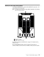
I/O board component locations
A simplified layout of the I/O board is shown in the following illustration.
1
Midplane connector
2
I/O function card slot
3
Voltage regulator module (VRM) connectors
4
Advanced System Management PCI adapter slot
5
USB 1 and USB 2 port connectors
6
PCI switch card connector
7
Hot-plug, 64-bit, PCI slots 10–12 (bus A, 33 MHz)
8
Hot-plug, 64-bit, PCI slots 8–9 (bus B, 66 MHz)
9
Hot-plug, 64-bit, PCI slots 6–7 (bus C, 66 MHz)
1
Hot-plug, 64-bit, PCI slots 1–5 (bus D, 33 MHz)
11
Hot-plug external attention/fail LED for PCI slot (green blink = attention,
amber = defective PCI adapter)
12
Hot-plug internal attention/fail LED for PCI slot (green blink = attention,
amber = defective PCI adapter)
13
Hot-plug power LED for PCI slot (green solid, on)
Your server has assigned PCI slots 10, 11, and 12 as PCI priority slots. The
system BIOS scans the PCI priority slots for startable (bootable) devices before
scanning the I/O function card.
Note:
If you install additional storage adapters and external hard disk drives, and
you do not want to change the startup hard disk drive, you must install the
adapters in PCI slots 1 through 9.
102
xSeries 370 User's Reference
Summary of Contents for eServer 370 xSeries
Page 1: ...User s Reference xSeries 370...
Page 2: ......
Page 3: ...IBM xSeries 370 User s Reference...
Page 32: ...16 xSeries 370 User s Reference...
Page 188: ...172 xSeries 370 User s Reference...


